The following was contributed by Dr. Allen Podell (he teaches Advanced Wireless Microwave Techniques at Besser Associates and is an expert in microwave engineering). It is a discussion of how T-coils can be derived from a lattice network with two baluns and more importantly, how their "ideality" (their frequency response) can be extended by including an extra shield wire. The words that follow are all those of Dr. Podell.
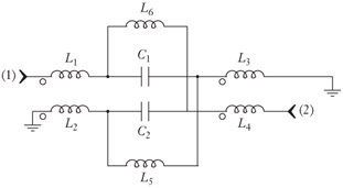
Start with a lattice network with 2 baluns.
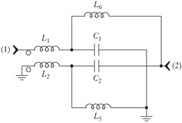
Eliminate one balun. This is free, as any 1 pin of the lattice can be grounded.
Parallel the balun with the inductor, and incorporate the inductance of the inductor. Now the balun does not need ferrite.
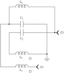
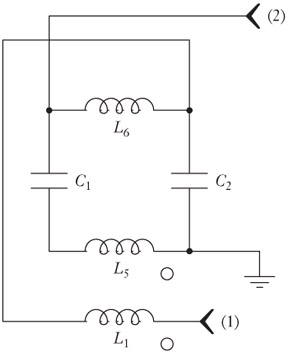
Next, put the two inductors on one coil form, as the currents through them are equal and opposite. The inductors can be tightly coupled, but the balun winding should only see the inductor winding with which it is forming a balun. There will be an added capacitance between the two inductors, but this is in parallel with capacitance already in the circuit.
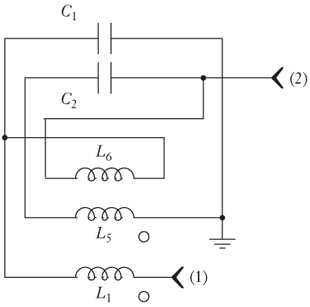
Move the capacitors so that it is clear that they parallel the inductor parasitic capacitance. This arrangement is close in performance to the original lattice in bandwidth.
This is a very good design. Next, move one capacitor so that it adds to the other. Since the coupling coefficient of the inductor pair is not unity, in effect this adds inductance in series with the capacitor that is moved, insofar as the operation of the lattice...
Copyright SciTech Publishing Inc. 2007 under license agreement with Books24x7


 TABLE OF CONTENTS