Wideband Amplifier Design

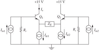
Figure 3-1 shows a basic difference amplifier. With this amplifier, if I in 2 is equal to zero, we would say that the amplifier is driven single ended. If I in 1 = -I in 2, then we say that the amplifier is driven differentially. If I in 1 = I in 2, then it is being driven with a common mode signal, and the resulting output should be zero. If it is driven differentially, then there must exist a "virtual ground" halfway inside of Z E. The equivalent circuit for this is shown in Figure 3-2. A virtual ground is a node in the circuit that is not actually tied to ground, but because of circuit symmetry, does not have any voltage change relative to ground. In the case of differential drive, we create two new (but identical) impedances called Z e whose sum is equal to Z E. At the center of these two impedances is a virtual ground. This means that we could replace the circuit in Figure 3-2 with a single-stage equivalent shown in Figure 3-3. If this looks familiar, it should; it is identical to the emitter-follower circuit we studied in the last chapter. The difference is that we are now going to look at the collector side of the circuit. To analyze the circuit, we will use the simplified model developed in the last chapter, as shown in Figure 3-4.