Wideband Amplifier Design

2.4: APPLYING THE MODELS

2.4 APPLYING THE MODELS

2.4.1 Input Impedance of the Emitter Follower

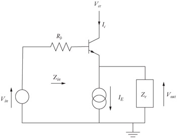
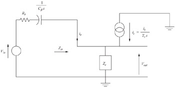
Substituting the high-frequency transistor model of Figure 2-6 into Figure 2-11 one obtains the circuit shown in Figure 2-12.


Figure 2-11: The emitter-follower circuit.

Figure 2-12: High-frequency equivalent circuit for the emitter follower.

I should note that I could have used the high-frequency model of Figure 2-7. For devices operated at high g m, this would not have made a difference in the final result. Either model will show that the device will oscillate under the right conditions. If a low- g m device is used, Figure 2-6 would provide a more accurate result. However, it is possible to derive everything using the model of Figure 2-7, then to substitute into the derived equations the extra capacitor of Figure 2-6 and regain the desired accuracy. I will use this technique in the coming pages in order to illustrate the concept. In most cases, one would know in advance if the more detailed model were required and use it to begin with. But sometimes it is simply easier to do it this way.

2.4.1.1 Solve For Z in

Start by solving for Z in as defined in Figure 2-12:

(2.10)

Summing node currents at the emitter

(2.11)

Because R b and X C? are assumed to be zero

(2.12)

Substituting

(2.13)

Rearranging

(2.14)

Substituting

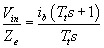
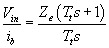
(2.15)

Equation (2.15) is an important equation, and we will use it frequently in the future.

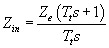
2.4.2 Let Z e =

UNLIMITED FREE
ACCESS
TO THE WORLD'S BEST IDEAS

SUBMIT
Already a GlobalSpec user? Log in.

This is embarrasing...

An error occurred while processing the form. Please try again in a few minutes.

Customize Your GlobalSpec Experience

Category: IC Electronic Filters
Finish!
Privacy Policy

This is embarrasing...

An error occurred while processing the form. Please try again in a few minutes.