 Intended as a textbook for electronic circuit analysis or a reference for practicing engineers, the book uses a self-study format with hundreds of worked examples to master difficult mathematic topics and circuit design issues. Computer programs using PSpice and MATLAB on the accompanying CD-ROM provide calculations and executables for visualizing and solving applications from industry. It covers the complex mathematical topics and concepts needed to understand and solve serious circuits problems.
 TABLE OF CONTENTS
 Network Analysis and Circuits
Chapter 12.3 - Phasor Diagram of Series RLC Circuit
12.3 PHASOR DIAGRAM OF SERIES RLC CIRCUIT
The nature of the phasor diagram of a series RLC circuit depends on the
frequency f of the applied signal in relation to the frequency of resonance f0.
Three different cases may be considered:
(i) f = fr, (ii) f < fr, and (iii) f > fr.
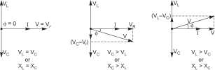
with f = f0, the reactance XL of inductor L equals the reactance of capacitor C.
The circuit is then purely resistive and the voltage V across the circuit is
in phase with the current I. The phasor diagram for the series RLC circuit
of Figure 12.4 for the series resonance condition is shown in Figure 12.4(a).
(a ) f = fr (b) f < fr (c) f > fr
FIGURE 12.4 Phasor diagram of the series RLC circuit.
With f < fr, the negative reactance Xc of capacitor C exceeds the positive
reactance XL of inductor L. Hence, the overall reactance is capacitive.
Current I leads the applied voltage V. Voltage VL leads the current by 90◦
while the voltage Vc lags behind current I by 90◦. The phasor diagram is
shown in Figure 12.4(b).
With f > fr, reactance XL exceeds the reactance Xc. The overall reactance
is inductive. Current I lags behind the applied voltage V. The phasor diagram
is shown in Figure 12.4(c).
Example 12.6. A series RLC circuit consists of a resistance R = 10Ω,
inductance L = 0.2H, and capacitance C = 0.2μF. Calculate the frequency
of resonance. A10 volts sinusoidal voltage at the frequency of resonance is
applied across the circuit. Draw the phasor diagram showing the value of
each phasor. Also calculate the values of (i) the current and the (ii) voltage
across R,C, and L and draw the phasor diagram when 10 volt 850 Hz voltage
is applied to the circuit.
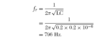
Solution: The frequency of resonance,
At

Hence, the phasor diagram is as shown in Figure 12.5.
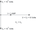
FIGURE 12.5
At
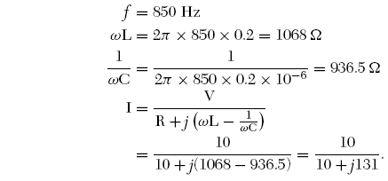
Magnitude
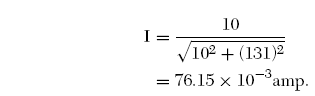
Let θ be the phase angle of current I relative to voltage V.
Then
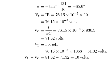
The phase diagram is shown in Figure 12.6.
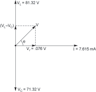
FIGURE 12.6
© 2026 Infinity Science Press