Flip-Flops Information
Last revised: October 2, 2024
Reviewed by: Scott Orlosky, consulting engineer
 Flip-flops are digital logic devices that synchronize changes in output state (1 or 0) according to a clocked input (edge-triggered). Because they use sequential logic, flip-flops control and are controlled by other circuitry in a specific sequence that is determined by both a control clock and enable/disable control signals.
Types
Several types of flip-flops are available.
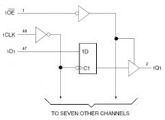
- D flip-flopshave one data input (D) and two outputs (Q and Q’).
- S-R flip-flopshave either set (S) and reset (R) inputs, or set (S) and clear (C) inputs. Depending on the input values, the two complementary outputs (Q and Q’) change according to the device’s logical function at the moment of the clock input’s active transition. Active high and active low S-R flip-flops are available.
- J-K flip-flops, a type of S-R device. Can act as a Set or a Reset device which avoids an indeterminate state that can occur with the SR flip-flop
- Toggle or T flip-flops, a single input version of the J-K flip-flop, toggles the output with each clock pulse. Typically, T flip-flops are used to develop counters, registers, and similar devices.
- Of these several types available, the D and JK version see the most use.
Specifications
Important specifications for Flip-flops include:
- Supply voltage
- Operating current
- Propagation delay
- Power dissipation
- Low level output current (sink)
- High level output current (source)
- Maximum clocking frequency
- Trigger type (rising or falling edge)
- Output characteristics
Supply voltages range from - 5 V to 5 V and include intermediate voltages such as -4.5 V, -3.3 V, -3 V, 1.2 V, 1.5 V, 1.8 V, 2.5 V, 3 V, 3.3 V, and 3.6 V.
Operating current is the minimum current needed for active operation.
The propagation delay is the time interval between the application of an input signal and the occurrence of the corresponding output.
 Power dissipation, the total power consumption of the device, is generally expressed in watts or milliwatts.
The low-level output current (IOL) is the output current to which gates sink.
The high-level output current (IOH) is the output current that gates source to a load.
The maximum clocking frequency (fMAX) is the highest rate in hertz (Hz) at which flip-flops can be triggered reliably.
Positive-edge, negative-edge, and master/slave triggers are available.
In terms of output characteristics, flip-flops are available with three-state, open-collector, and complementary outputs. Output enable (OE) inputs have an enable pin for the output. Output enable can allow for circuit debouncing, multiplexing or using tri-state logic
Variations in Flip-Flop Construction
Selecting flip-flops requires an analysis of logic families. Transistor-transistor logic (TTL) and related technologies such as Fairchild advanced Schottky TTL (FAST) use transistors as digital switches. By contrast, emitter coupled logic (ECL) uses transistors to steer current through gates that compute logical functions. Another logic family, complementary metal-oxide semiconductor (CMOS), uses a combination of p-type and n-type metal-oxide-semiconductor field effect transistors (MOSFETs) to implement logic gates and other digital circuits. Logic families for flip-flops include cross-bar switch technology (CBT), Gallium arsenide (GaAs), integrated injection logic (I2L) and silicon on sapphire (SOS). Gunning with transceiver logic (GTL) and gunning with transceiver logic plus (GTLP) are also available.
Package Options
Flip-flops are available in a variety of IC package types and with different numbers of pins and flip-flops. Basic IC package types for flip-flops include:
- Ball grid array (BGA)
- Quad flat package (QFP)
- Single in-line package (SIP)
- Dual in-line package (DIP)
Many packaging variants are available. For example, BGA variants include plastic-ball grid array (PBGA) and tape-ball grid array (TBGA). QFP variants include low-profile quad flat package (LQFP) and thin quad flat package (TQFP). DIPs are available in either ceramic (CDIP) or plastic (PDIP). Other IC package types include small outline package (SOP), thin small outline package (TSOP), and shrink small outline package (SSOP). Commonly, DIP and SMD packages are popular packaging options.
Standards
MIL-M-38510/331 — Microcircuits, digital, bipolar, low-power Schottky TTL, flip-flops, cascadable, monolithic silicon
DSCC-DWG-95575 — Microcircuit, digital, bipolar, TTL, dual J-K flip-flops with preset and clear, monolithic silicon
SMD 5962-90695 — Microcircuit, digital, bipolar, advanced low power Schottky, TTL, 8-bit bus interface flip-flops with three-state outputs, monolithic silicon
Flip-Flops FAQs
What are the applications of flip-flops?
Flip-flops are used in various applications including data storage for storing binary data; as counters used in digital counters to count pulses; as shift registers used in shift registers for data transfer; and as finite state machines, used in designing finite state machines that go through a sequence of states based on input pulses.
What is a timing diagram and why is it important?
A timing diagram is a graphical representation used to describe the operation of sequential circuits, including flip-flops. It shows the relationship between the input signals and the resulting output states over time. This is crucial for understanding the behavior of flip-flops in a circuit. It also is useful in describing both flip-flops, which are edge triggered and latches, which are level triggered.
What is the role of a clock pulse in flip-flops?
The clock pulse is essential for the operation of flip-flops. It triggers the state change in the flip-flop, either on the rising edge (positive edge) or falling edge (negative edge) of the clock signal.
What are the characteristic tables for flip-flops?
Characteristic tables describe the behavior of flip-flops by showing the next state of the output based on the current state and input signals. For example, the characteristic table for a D flip-flop shows that the next state is the same as the input data.
What is a state diagram?
A state diagram is a graphical representation of a finite state machine, showing the sequence of states through which the circuit passes based on input pulses. It is a useful tool for understanding the operation of sequential circuits involving flip-flops.
What are the differences between TTL and CMOS logic families?
The differences between TTL (Transistor-Transistor Logic) and CMOS (Complementary Metal-Oxide-Semiconductor) logic families are:
Technology and Components
TTL uses transistors as digital switches. Specifically, it employs bipolar junction transistors (BJTs) to perform logic operations. While CMOS use a combination of p-type and n-type metal-oxide-semiconductor field-effect transistors (MOSFETs) to implement logic gates and other digital circuits.
Power Consumption
TTLs generally consumes more power compared to CMOS. This is due to the continuous current flow through the transistors even when they are not switching. Meanwhile, CMOS is known for its low power consumption, especially in static conditions where no switching occurs. This makes CMOS more suitable for battery-operated devices.
Switching Speed
TTL is typically faster than CMOS in terms of switching speed. This makes TTL suitable for high-speed applications. While CMOS has improved significantly over the years, it is generally slower than TTL in switching speed due to the higher capacitance of MOSFETs.
Noise Immunity. TTL has lower noise immunity compared to CMOS. This means TTL circuits are more susceptible to noise and interference. CMOS offers higher noise immunity, making it more robust in noisy environments.
Voltage Levels
TTL operates at a standard voltage level of 5 V while CMOS can operate at a wide range of voltage levels, typically from 3 V to 15 V, providing more flexibility in design.
Cost
TTL is generally more expensive due to the complexity of the manufacturing process involving BJTs while CMOS is usually cheaper to produce, especially in large volumes, due to the simpler manufacturing process of MOSFETs.
Applications
TTLs are commonly used in applications requiring high speed and moderate power consumption, such as in older computer systems and industrial controls. While CMOS is widely used in modern electronics, including microprocessors, microcontrollers, and other digital logic circuits, due to its low power consumption and high noise immunity.
These differences highlight the strengths and weaknesses of each logic family, making them suitable for different types of applications.
Flip-Flop Media Gallery
References
GlobalSpec—Digital Parallel and Serial Converters
GlobalSpec—Hands-on Electronics: A One-Semester Course for Class Instruction or Self-Study
Image credits:
- -3.3 V
- 1.2 V
- 1.5 V
- 1.8 V
- 2.5 V
- 3 V
- 3-State Output
- 3.3 V
- 3.6V
- 5 V
- Advanced CMOS
- BGA
- CDIP
- D
- DIP
- ESD Protection
- Emitter Coupled Logic (ECL)
- Fast CMOS
- High-Speed CMOS
- J-K
- LCCC
- Low Voltage CMOS
- Master-slave
- Negative-edge Triggered
- Open-Drain Output
- Output Enable Input (OE)
- PDIP
- PLCC
- Positive-edge Triggered
- QFP
- SOIC
- SOP
- SSOP
- Standard CMOS / CMOS 4000
- T
- TQFP
- TSSOP
- TVSOP
- Transistor-Transistor Logic (TTL)