Transistors Information

Transistors are small, versatile semiconductor devices designed to switch or amplify electronic signals and power. Almost all electronic devices today contain one or more transistors. Some transistors are individually packaged, but many more are embedded in integrated circuits. In these circuits, the number of transistors can range from a few to a few billion. The transistor is considered to be one of the most important inventions of the 20th century because of its abundant use in most modern circuits and electronic systems.
Composition
Transistors can be divided into types based on the composition and consequently the polarity of the transistor.
Bipolar Transistors
Bipolar transistors, also called bipolar junction transistors (BJTs), are the most commonly used transistors. They are composed of a thin piece of either p-type or n-type semiconductor material (explained further on) between two thicker layers of the opposite type. These transistors consist of three lead components: a base, collector, and emitter.
- The base is the lead responsible for activating the transistor. It is the gate controller device for the larger electrical supply.
- The collector is the positive lead and the larger electrical supply.
- The emitter is the negative lead and the outlet for the larger electrical supply.

A simple transistor indicating its three main components. Image Credit: Technology Student
NPN and PNP are the two standard types of transistors. The letters refer to the order of semiconductor layers which make up the leads; N-type layers are composed of negative charge carriers and have excess electrons, and P-type layers are composed of positive charge carriers and have a lack of electrons. In semiconductors, free electrons are negatively charged and holes in the material are positively charged.
NPN transistors have collector and emitter leads made of N-type material and a base lead made of P-type material. They use electrons as current carriers. They are more common because they are easier to construct from silicon.
PNP transistors have collector and emitter leads made of P-type material and a base lead made of N-type material. They use holes (spots lacking electrons) as current carriers. They function nearly the same as NPN transistors, except that the main flow of current in these is controlled by altering the number of holes in the base. The negative and positive connections made by a PNP transistor are also the reverse of those of an NPN.

Composition and current flow differences between a PNP and an NPN transistor. Image Credit: PhysLink.com
Field Effect (Unipolar) Transistors
Field effect transistors (FETs), also called unipolar transistors, are transistors with only two layers of semiconductor material. They include gate, source, and drain components.
- The gate is the semiconductor layer and terminal that modulates current via an applied voltage.
- The source is where current enters the channel.
- The drain is where current leaves the channel.
The composition of a FET is depicted in the image below.
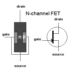
Image Credit: PhysLink.com
In operation, electricity flows through the first semiconductive layer (called the channel). The voltage connected to the second semiconductive layer (the gate) controls the strength of the current in the channel by interfering with the current flow.
How Transistors Work
The workings of a transistors can be explained on both functional and theoretical levels.
Functional Understanding
Transistors can function as switches and amplifiers. During operation, supplied voltage modifies the flow of the electrical current by electron addition or flow interruption. This allows small changes in voltage to cause proportionally larger changes in output current, resulting in amplification. The current which runs through a transistor also can also function as a switching mechanism. A simple visual analogy can be used to understand transistor operation.
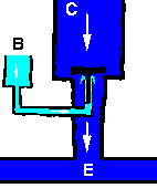
Transistor operation as depicted by a water flow analogy. Image Credit: Satcure-focus.com
The diagram above can be used to represent a transistor (in this case a bipolar type), where water flow represents current flow. Initially, a water reservoir (supply voltage) is supplied to the collector (C) and remains constant so as not to overload the transistor capacity. By modifying the current from the base channel (B) by increasing voltage, the gate (switch) moves, allowing a proportionally larger amount of current to flow from the collector to the emitter (E).
Theoretical Understanding
While two-terminal devices are described with one voltage and one current, transistors (three terminal devices) are described with three voltages and three currents. In a BJT, the three voltages are the voltages between any two terminals, represented by VBE, VCE, and VCB. The currents are referred to as the emitter current (IE), collector current (IC), and base current (IB). The following figure shows the construction layout, the symbol, and the direction and polarities of currents and voltages in an NPN transistor. For a PNP transistor these currents and voltages have opposite polarities.
![]()
The transistor can produce a large output (IC) with very small input (IB). The factor by which the output current (IC) is bigger than the controlling or input current (IB) is called the DC current gain (β) of the amplifier. Its value normally is given by the manufacturer and is sometimes represented by the symbol hFE. It can be found by the approximate formula:
![]()
This video provides further explanation of the theory behind how transistors work:
Video Credit: dizzo95
Selection Criteria
When selecting transistors, industrial buyers should consider the transistor type and its performance specifications, design parameters, and application.
Types
Different types of transistors may have advantages which make them preferable for certain applications.
-
Bipolar transistors are preferred for high speed switching applications and as high-power amplifiers for systems with large current flow.
-
Field effect transistors are preferred for weak-signal applications (e.g. simple wireless communications and broadcast receivers) and in high-impedance systems.
Performance Specifications 
Transistors can be described based on a number of parameters and specifications.
Collector current (IC) describes the maximum allowable current load in the collector. It is measured in milliamps (mA) or amps (A) depending on the power of the transistor. If the current in the collector exceeds this parameter, the transistor may be damaged from overload.
Power dissipation (PD or Ptot) describes the power dissipation of the transistor. It is typically measured in watts. Actual dissipation is determined by multiplying the voltage across the transistor and the current through the collector. It is normally quoted for an ambient external temperature of 25°C
Current gain (hFE) or (β) describes the current gain of the transistor. It defines the factor by which current will be amplified in a transistor.
Frequency transition (fT) is the frequency at which current gain falls to unity. It is measured in MegaHertz (MHz). In most cases, the transistor should operate well below this frequency.
Collector-to-emitter breakdown voltage (VCE) is the maximum allowable voltage between the collector and emitter. It is measured in volts. Voltages which exceed this rating may damage the corresponding transistor.
Design Parameters
Transistors can be characterized based on a number of design parameters, ranging from case style to material type.
Case style- Transistors can be designed based on a wide variety of case styles. TOxx case codes describe leaded devices and SOTxxx case codes describe surface mounted devices.
Material - Transistors are most commonly composed of one of two semi-conductive materials: silicon or germanium. Specific levels of impurities (dopants) are added to alter or enhance the performance properties of the transistor needed for the application. Although germanium has more desirable electrical properties, silicon is much more commonly used because of its reliability and low cost.
Application
Selecting the right transistor can be very application specific. For this reason, many product sheets will include general or specific applications for different transistor products. Some general applications include:
- Low/medium/high power
- General purpose
- Low noise
- High gain
Some specific applications include:
- Mixer
- UHF/VHF amplifier
- Darlington amplifier
- Wide band amplifier
Standards
BS IEC 60747-7 - Semiconductor devices - discrete devices part 7: Bipolar transistors
References
All About Circuits - Junction Field-Effect Transistors
Electronics Club - Transistors
PhysLink - How does a transistor work?
WhatIS.com - field effect transistor (FET)
NTE Electronics, Inc. - Silicon Transistor Selector Guide
Image Credit:
Digi-Key Corporation | Allied Electronics, Inc. | Newark / element14
- Automotive
- Bipolar RF Transistors
- CMOS
- Commercial
- Complementary
- Darlington
- FPAK
- General Purpose BJT
- HEMT
- HFET
- IGBT
- Industrial
- JFET
- MESFET
- MOSFET
- MOSFET RF Transistors
- Military
- N-Channel
- NPN
- P-Channel
- PHEMT
- PNP
- Power BJT Transistors
- Power MOSFET
- SO-8
- SOT123
- SOT143
- SOT223
- SOT23
- SOT25
- SOT26
- SOT3
- SOT323
- SOT89
- TO-202
- TO-220
- TO-247
- TO-251 / TO-252
- TO-263
- TO-3
- TO-39
- TO-8
- TO-92
- transistors equivalent
- RF power transistor
- unijunction transistor
- transistor manual
- data transistor equivalents
- transistor replacement
- transistor germanium
- transistor katalog
- buy transistor
- transistor package
- high frequency transistors
- microwave transistor
- ac127 transistor
- chemFET
- gan power transistor
- HEMT
- mrf transistors motorola
- RF power amplifier transistor
- sl100 transistor
- trw transistor
- UHF transistor
- DC Biasing HEMT Transistor
- HEMT transistors
- LDMOS Power Transistor
- 100 amp transistors
- 100a transistor
- 100V transistor
- 100W transistor
- 10a transistor
- 10W transistor