Gear Geometry and Applied Theory, Second Edtion

An invaluable reference for designers, theoreticians, students, and manufacturers, this text covers the theory, design, geometry, and manufacture of all types of gears and gear drives.
The concept of relative velocity is used for the derivation of the equation of meshing (see Section 6.1) and for the derivation of centrodes and axodes (see Chapter 3). Consider that two bodies are rotated about crossed axes with angular velocities ? (1) and ? (2), respectively (Fig. 2.1.1). Vector ? (1) passes through the origin of fixed coordinate system S f that is employed in the gear housing. The twist angle is ? and the shortest distance is E. Point M is common to both rotating bodies. The relative velocity of point M (1) of body 1 with respect to point M (2) of body 2 is represented by the equation
where v ( i ) is the velocity of point M ( i ) of body i ( i = 1 , 2).
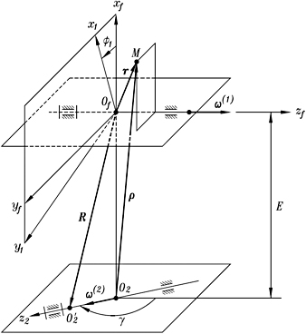
The velocity v (1) is represented by the equation
where r is the position vector that is drawn to point M from an arbitrary point on the line of action of ? (1), for instance, from point O f. Similarly, we may represent the velocity v (2) by
where ? is drawn to point M from an arbitrary point on the line of action of ? (2), for instance, from point O 2. An alternative equation for v (2) is based on...