Gear Geometry and Applied Theory, Second Edtion

An invaluable reference for designers, theoreticians, students, and manufacturers, this text covers the theory, design, geometry, and manufacture of all types of gears and gear drives.
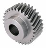
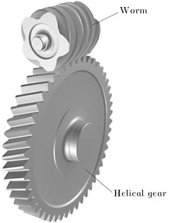
Involute helical gears are widely applied in the industry for transformation of rotation between parallel and crossed axes. Figure 16.1.1 shows an involute helical gear drive with crossed axes in 3D-space. A gear drive formed by a helical gear and a worm gear is a particular case of a gear drive with crossed axes (Figure 16.1.2). Gear tooth surfaces are in line contact for involute helical gear drives with parallel axes and in point contact for involute helical gear drives with crossed axes.

The theory of involute gears and research in this area have been presented by Litvin [1968], Colbourne [1987], Townsend [1991], and Litvin et al. [1999, 2001a, 2001c, 2001d] and the theory of shaving and honing technological processes are discussed in the works of Townsend [1991] and Litvin et al. [2001a]. Despite the broad investigation that has been accomplished in this area, the quality of misaligned involute helical gear drives is still a concern of manufacturers and designers. The main defects of such misaligned gear drives are (i) appearance of edge contact, (ii) high levels of vibration, and (iii) the shift of the bearing contact far from the central location.
To overcome the defects mentioned above, some corrections of gear geometry have been applied in the past: (i) correction of the lead angle of the pinion (requires regrinding), and (ii) crowning in...