Gear Geometry and Applied Theory, Second Edtion

An invaluable reference for designers, theoreticians, students, and manufacturers, this text covers the theory, design, geometry, and manufacture of all types of gears and gear drives.
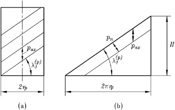
Figure 19.3.1(a) shows the pitch diameter d p of the worm ordinary pitch cylinder; p ax is the axial distance between the neighboring threads of the worm, which is measured along the generatrix of the pitch cylinder. We designate with P ax the ratio P ax = ?/p ax. The worm pitch diameter may be chosen as
The value of q depends on the number N 1 of threads of the worm and the number N 2 of gear teeth and may be picked up from a recommended set (7 ? q ? 25).
Let us develop the pitch cylinder on a plane [Fig. 19.3.1(b)]. The helix for each worm thread is represented by a straight line. The distance p ax between the neighboring straight lines is
where N 1 is the number of worm threads, and H is the lead. Considering as known r p and P ax, we can determine the lead angle on the pitch cylinder from the following equation [Fig. 19.3.1(b)]:
The lead angles on the worm operating pitch cylinder and ordinary pitch cylinder are related as
where p = H/(2 ?) is the screw parameter. Equations (19.3.3) and (19.3.4) yield
where