Gear Geometry and Applied Theory, Second Edtion

An invaluable reference for designers, theoreticians, students, and manufacturers, this text covers the theory, design, geometry, and manufacture of all types of gears and gear drives.
Generation of worms, screws, and helical gears by milling cutters or grinding wheels is considered. Two types of tools for this process are applied: (i) the finger-shaped tool, and (ii) the disk-shaped one. Figures 24.1.1(a) and 24.1.2 show the finger-shaped and disk-shaped milling cutters, respectively. There are two main problems of design when generation of helicoids is considered: (i) the tool surface ? c is given and surface ? p of the workpiece must be determined, and (ii) the inverse problem, when surface ? p is given and ? c is to be determined.
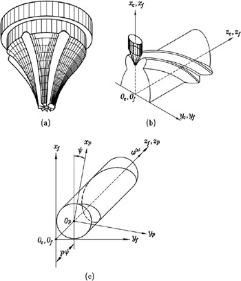
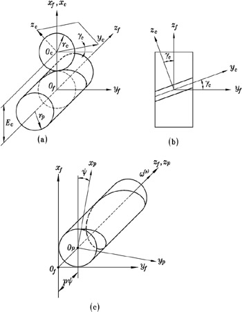
Henceforth, we use coordinate systems S c, S p, and S f , which are rigidly connected to the tool, the workpiece, and the frame of the cutting machine, respectively. Figure 24.1.3 shows the installation of the disk-shaped tool. Here, r p is the pitch radius of the workpiece; r c is the cutter mean radius; E c and ? c are the shortest distance and the crossing angle between the axes of rotation of the tool and the workpiece. In the case of application of the finger-shaped cutter, coordinate systems S c and S f coincide, and the tool axis is x c [Fig. 24.1.1(b)].