Mastering AutoCAD Civil 3D 2008

Full of advanced techniques and insider tips, this tutorial-based guide will help you understand concepts, create perfect designs, and manage every stage of the project.
 TABLE OF CONTENTS
 Cross sections are used in Civil 3D to allow the user to have a graphic confirmation of design intent, as well as to calculate the quantities of materials used in a design. Sections must have at least two types of Civil 3D objects to be created: an alignment and a surface. Other objects, such as pipes, structures, and corridor components, can be sampled in a sample line group, which is used to create the graphical section that is displayed in a section view. These section views and sections remain dynamic throughout the design process, reflecting any changes made to the sampled information. This reduces potential errors in materials reports, keeping often costly mistakes from happening during the construction process.
In this chapter, you will learn how to:
Create sample lines
Create section views
Define materials
Generate volume reports
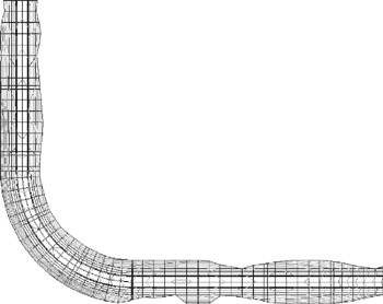
Before you create sample lines, you often start with a corridor. The corridor allows you to display the materials being used, as well as to show the new surface with cut-and-fill areas. In this chapter, the corridor is a relatively short roadway (1,340 ?) designed for a residential subdivision (see Figure 13.1).
This corridor has both a top surface and a base surface created for inclusion in the sample line group, as shown in Figure 13.2. Creating surfaces from the different links and feature lines in a corridor allow you to use sections to calculate volumes between those surfaces. These...