Mastering AutoCAD Civil 3D 2008

Full of advanced techniques and insider tips, this tutorial-based guide will help you understand concepts, create perfect designs, and manage every stage of the project.
 TABLE OF CONTENTS
 Once you 've understood the parts used to design and construct pipe networks, it's time to assemble those parts into a system or network. In this chapter, you'll learn to:
Create a pipe network by layout
Create an alignment from network parts and draw parts in profile view
Label a pipe network in plan and profile
Create a dynamic pipe table
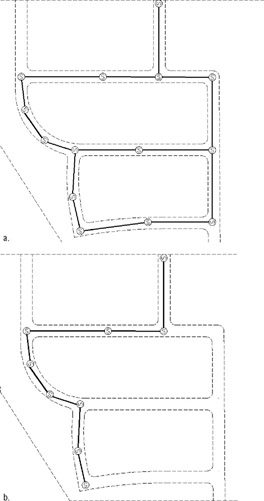
Parts in a pipe network have relationships that follow a network paradigm. A pipe network can have many branches, like the one in Figure 15.1a. In most cases, the pipes and structures in your network will be connected to each other; however, they don't necessarily have to be physically touching to be included in the same pipe network.
Land Desktop with civil design and some other civil engineering-design programs do not design piping systems using a network paradigm; instead, they use a branch-by-branch or "run" paradigm (see Figure 15.1b). Though it is possible to separate your branches into their own separate pipe networks in Civil 3D, you will find the most power and flexibility in your design if you change your thinking from a "run-by-run" to a network paradigm.
Pipes are components of a pipe network that primarily represent pipes but can be used to represent any type of conduit such as culverts, gas lines, or utility cables. They can be...