Operation and Modeling of the MOS Transistor

Appendix J: Drain Current Formulation Using Quasi-Fermi Potentials

OVERVIEW

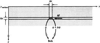
In Sec. 4.3 we evaluated the drain current caused by both drift and diffusion. The current components caused by each of these two phenomena were kept separate. In this appendix we present an alternative approach, resulting in a compact formulation which combines the two effects. [1] We consider the flow of electrons as laminar flow. That is, we assume that the total current I DS is the sum of elemental currents ? I, each flowing horizontally in an inversion layer slice parallel to the surface, having width W and depth ? y, centered at point y, as shown in Fig. J.1. In the general case, we will have for the current in each slice, allowing ? y to become a differential,


Figure J.1

where it should be kept in mind that our direction for the current is from right to left, as shown in Fig. J.1. The drift component is, from (1.3.11),


The diffusion component is, from (1.3.17) and (1.3.18),


At the source end of the channel, n will be given by (I.1), with V CB = V SB, and at the drain end of the channel, n will be given by that relation with V CB = V DB. For a position x in the channel, a similar relation can be written with V CB replaced by a quantity V( x):


where V(0) = V SB and V(

UNLIMITED FREE
ACCESS
TO THE WORLD'S BEST IDEAS

SUBMIT
Already a GlobalSpec user? Log in.

This is embarrasing...

An error occurred while processing the form. Please try again in a few minutes.

Customize Your GlobalSpec Experience

Category: Power MOSFET
Finish!
Privacy Policy

This is embarrasing...

An error occurred while processing the form. Please try again in a few minutes.