Practical Microstrip Design and Applications

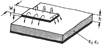
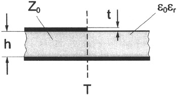
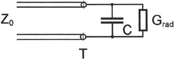
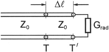
The open-ended microstrip line, shown in Figure 6.3, is frequently used in microwave integrated circuits as a tuning stub, in multistub filters and transmission line resonators, or as radiating elements in microstrip antennas. The reference plane of the open is denoted by T and relates to the physical termination (Figure 6.4). Different physical effects occur at the open and must be considered in an equivalent circuit model. Similar to the fringing electrical field at the sides of the microstrip line, there is also an electrical stray field at the open termination, which can be equivalently described by an open end capacitance, as shown in Figure 6.5. This capacitance can be calculated on the basis of an electrostatic method [4]. Alternatively, the end capacitance also can be described by a short hypothetical line of length ? l with the same given microstrip line parameters as illustrated in Figure 6.6 (Section 6.1.1). Losses are caused by the excitation of substrate surface waves on the dielectrically loaded metal plate as discussed in Chapter 3, and in radiation fields. Both effects are equivalently described by a radiation resistance R rad or the inverse of a radiation conductance G rad, which will be discussed in the following section.


Comparing the electric...
