6.4 Stub
When the branch arm of a T-junction is terminated by an open-ended microstrip transmission line, the composed circuit acts like a filter. As illustrated in Figure 6.63, the electrical length l leff is calculated as
| (6.101) | 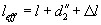
|
where l is the physical length of the shunt arm,  the location of the stub reference plane with respect to the strip edge of main line, and ? l the line extension of the open-ended stub. When the electrical length is
| (6.102) | 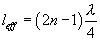
|
where n = 1,2,3,..., then the microstrip circuit behaves like a band-stop filter at the resonance wavelength ?. With the stub resonant frequency 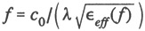 , the resonance condition (6.102) reads
| (6.103) | 
|
At resonance frequency, no power is transmitted. All incident power on the main line is reflected. The circuit acts as a bandstop filter.
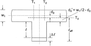 Figure 6.63: Reference planes and relevant geometric stub parameters.
 At resonance frequencies, where the effective stub length is a multiple of half-wavelengths,
| (6.104) | 
|
where n = 0, 1, 2,..., all incident power is transmitted. The circuit acts as a bandpass filter. Figure 6.64 shows an example of the measured magnitude of transmission coefficient of a stub filter element on Polyguide substrate material ( ? r = 2.32, h = 1.6 mm) [32]. A transmission zero is found at 4 GHz when the effective stub length is one quarter-wavelength. At the third quarter-wavelength resonance (approximately 11 GHz), no complete power transfer suppression is observed. This may be explained by the distributed...