Secrets of RF Circuit Design, Third Edition
The measurement of the values of inductors ( L) and capacitors ( C) at radio frequencies differs somewhat from the same measurements at low frequencies. Although similarities exist, the RF measurement is a bit more complicated. One of the reasons for this situation is that stray or distributed inductance and capacitance values of the test set-up will affect the results. Another reason is that capacitors and inductors are not ideal components but rather all capacitors have some inductance and all inductors have capacitance. In this chapter we will take a look at several methods for making such measurements.
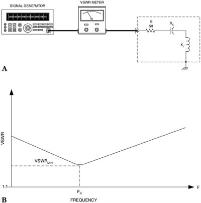
When a load impedance ( R + jX ) is connected across an RF source the maximum power transfer occurs when the load impedance ( Z L) and source ( Z S) impedances are equal ( Z L = Z S). If these impedances are not equal, then the voltage standing wave ratio (VSWR) will indicate the degree of mismatch. We can use this phenomenon to measure values of inductance and capacitance using the scheme shown in Fig. 16-1A. The instrumentation required includes a signal generator or other signal source and a VSWR meter or VSWR analyzer.
Some VSWR instruments require a transmitter for excitation, but others will accept the lower signal levels that can be produced by a signal generator. An alternative device is the SWR...