Overview
In radio-frequency electronics, a mixer is a nonlinear circuit or device that permits frequency conversion by the process of heterodyning. Mixers are used in the front end of the most common form of radio, the superheterodyne (regardless of wave band), in certain electronic instruments and in certain measurement schemes (receiver dynamic range, oscillator phase noise, etc.).
The block diagram for a basic mixer system is shown in Fig. 20-1; this diagram is generic in form, but it also represents the front end of superheterodyne radio receivers. The mixer has three ports: F 1 receives a low-level signal and would correspond to the RF input from the aerial in radio receivers, F 2 is a high-level signal and corresponds to the local oscillator (LO) in superhet radios; and F 3 is the resultant mixer product (corresponding to the intermediate frequency or IF in superhet radios). These frequencies are related by:
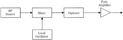 Figure 20-1: Block diagram of a mixer circuit.
 | (20-1) | 
|
where<i class="emphasis"> F</i><sub1</sub>, <i class="emphasis">F</i><sub2</sub>, and <i class="emphasis">F</i><sub3</sub> are as described<i class="emphasis"> m</i> and <i class="emphasis">n</i> are counting numbers (zero plus integers 0, 1, 2, 3, <span class="unicode"> </span>).
In any given system, m and n can be zero, or any integer, but in practical circuits, it is common to consider only the first-, second-, and third-order products. For sake of simplicity, let s consider a first-order circuit ( m = n = 1). Such...