A vector (Fig. 18-1A) is a graphical device that is used to define the magnitude and direction (both are needed) of a quantity or physical phenomena. The length of the arrow defines the magnitude of the quantity, while the direction in which it is pointing defines the direction of action of the quantity being represented.
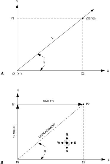
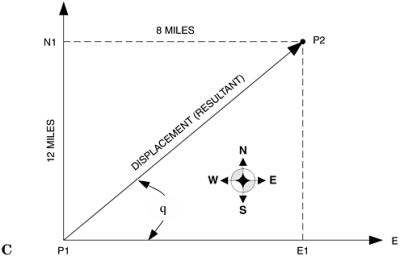 Figure 18-1: (A) Simple vector system; (B) N-E vector system; (C) Displacement vector.
 Vectors can be used in combination with each other. For example, in Fig. 18-1B we see a pair of displacement vectors that define a starting position ( P 1) and a final position ( P 2) for a person who traveled from point P 1 12 miles north and then 8 miles east to arrive at point P 2. The displacement in this system is the hypotenuse of the right triangle formed by the north vector and the east vector. This concept was once illustrated vividly by a university bumper sticker s directions to get to a rival school: North til you smell it, east til you step in it.
Figure 18-1C shows a calculations trick with vectors that is used a lot in engineering, science, and especially electronics. We can translate a vector parallel to its original direction and still treat it as valid. The east vector (E) has been translated parallel to its original position so that its tail is at the same point as the tail of the...
Copyright The McGraw-Hill Companies, Inc. 2001 under license agreement with Books24x7