Analysis of Piezoelectric Devices

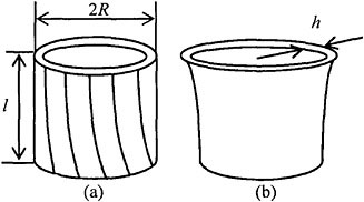
Consider the two modes of a circular cylindrical shell of radius R, length l, and thickness h shown in Fig. 7.4.1. The bottom of the shell is fixed and the top is free.

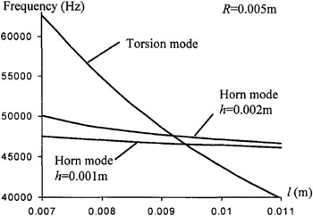
First, we note that material particles move in perpendicular directions in these two modes. Furthermore, the frequency of the torsional mode depends strongly on the length l, while the frequency of the horn mode is sensitive to the radius R. Therefore, by adjusting geometric parameters, the frequencies of these two modes can be tuned as close as desired. For simplicity consider a shell made of an isotropic elastic material. A finite element modal analysis by the commercial software ANSYS shows that the frequencies depend on the geometric parameters as shown in Fig. 7.3.2.

For certain values of the geometric parameters the frequencies of the two modes become the same (where the curves intersect). The above observations show that the torsional and horn modes can be used to make gyroscopes.
Consider the ceramic piezoelectric shell in Fig. 7.4.3 [81]. The shell is inhomogeneous. For the excitation of the horn mode and the detection of the torsional mode, the two portions of the shell are poled in different directions. In the driving portion a 2< z
