Incremental Rotary Encoders Information
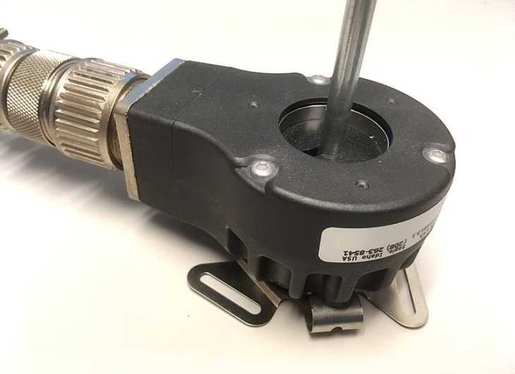
Figure 1: Rotary incremental encoder. Source: Lambtron/CC BY-SA 4.0
An incremental rotary encoder converts angular motion or the position of a shaft to either analog or digital code. Incremental encoders are often used in feedback systems. These encoders translate rotational movement into electrical signals and allow for more precise control of automated systems.
There are two primary types of rotary encoders: incremental and absolute. Incremental encoders can measure distance, position, and speed. They can be used in light or heavy applications and are commonly used in servo motors. They differ from absolute encoders that measure the absolute position as an angle. Instead, incremental rotary encoders report the change in position. They produce alternating high and low pulses as the device rotates, which indicates the speed and direction of the rotation.
The required level of accuracy in speed or position control is a crucial part of encoder selection. As system requirements vary greatly, there are many types of incremental rotary encoders that employ a variety of different technologies.
Technology
There are various technologies that enable incremental encoding. There are advantages and disadvantages to each technology and selection should be based on the specific use cases or system requirements.
Optical
Incremental Encoder (Shaft Encoder)—How it works
Video: How optical encoders work. Source: Learnchannel
Optical encoders include an LED that passes light through a disc with concentric tracks with openings cut into it. The windows of the tracks may be offset so that each revolution will generate a different light and dark pattern. On the other side of the rotary encoder is a mask that is grooved with tracks and openings. An LED shines light through the moving disk onto the mask of the optical rotary encoder onto the sensor.
Optical encoders require the system to be free of dirt and grime to prevent the blocking of LEDs and photodiodes. These encoders are limited to the lifetime of the LEDs with LED lifetimes being reduced at high temperatures. Optical encoders are very common in industrial applications and often boast higher resolutions and accuracy than other encoder technologies. This type of encoder can also produce a quadrature sequence.
Mechanical
A mechanical encoder relies on mechanical contacts that make or break electrical connections. A metal brush is attached to the rotating components and makes periodic contact with an adjacent stationary component next to the center shaft.
This solution is passive but may be complex mechanically. Mechanical encoders tend to not perform well in dirty or harsh environments and are prone to weather. They also require debounce timing. Under normal operation, the mechanical contacts experience wear, which limits the life of mechanical rotary encoders. Mechanical configurations are not suited for high operating speeds.
Magnetic
https://www.youtube.com/watch?v=wcgoxDSnCwQ
Video: Advantages of bearingless encoders. Source: Dynapar
Magnetic gear tooth incremental rotary encoders use a magnetic sensor with a ferromagnetic gear with teeth. The teeth moving passed the sensor changes the magnetic field and generates a voltage pulse. This data can be used to determine the speed of rotation. The output resolution is limited by the number of gear teeth with typical resolutions being limited to 120 or 240 pulses per revolution.
A magneto-resistive encoder uses a circular magnet with multiple north and south poles. The resolution of the encoder is determined by the number of poles and sensors. The sensors detect changes in the magnetic field as the disk rotates and converts this data into a sine wave. The sensors may be Hall effect devices and sense voltage changes. The number of pole pairs, the number of sensors, and the characteristics of the electric circuit determine the resolution of the magnetic encoders.
Magnetic encoders are inexpensive, compact, and reliable. They can also be contactless and the sensors can be solid-state electronics. Magnetic fields can permeate through materials and are not affected by common contaminants. The electrical circuitry can be sealed from the environment as well. When magnetic rotary encoders are encapsulated, they are extremely robust as a component and can handle varying operating temperatures, shock, and vibration. As the input sensing and output signaling are essentially digital, there is little noise increasing accuracy.
This type of encoder is commonly used in pulp and paper mills and in steel manufacturing settings.

Figure 2: Pipe manufacturing. Source: Unsplash
Fiber Optic
Fiber optic encoders are used where conventional electronics-based encoders and resolvers are insufficient. They are used to sense the motion and speed of a motor shaft. Fiber optic rotary encoders are designed to be used in environments that require long-distance transmission and high noise resistance. The fiber optic link can typically span distances up to two miles and even greater.
Designs
Ring
Ring encoders are large-diameter rotary encoders. Due to their size, ring incremental encoders are often used for parts with large diameters. Many ring encoders use optical technology. The optical ring-shaped grating rotates relative to an optical sensor that is stationary beside the ring. These types of encoders work well for high-precision applications in favorable environments. Ring magnetic encoders are more suited for harsh environments.
Bearingless
This type of encoder generates angle, position, and speed information without physical contact with the rotating shaft. As a result, bearings are not required within the encoder. Bearingless encoders are typically designed with magnetic sensing technology and are resilient to harsh environments. This type of encoder is suited for heavy-duty applications with extreme temperatures, shock vibration, and contaminants. Their unique construction allows them to withstand conditions that other types of encoders cannot.
Bearingless encoders allow for wear-free operation as magnetic properties allow for the sensor unit and measuring elements to be mechanically separated. The lack of physical wear can prolong the life of the component.
Hollow Shaft
Hollow shaft encoders can directly mount onto a motor shaft. They do not require motor shaft alignment in accordance with the encoder.
Miniature
Incremental rotary encoders for use in tight spaces may be miniature in design. Miniature rotary encoders are used in applications with major limitations to the allowable weight and space of the encoder. They are often used in robotic joints and servo control applications.
Signal Output
Pulse and Direction
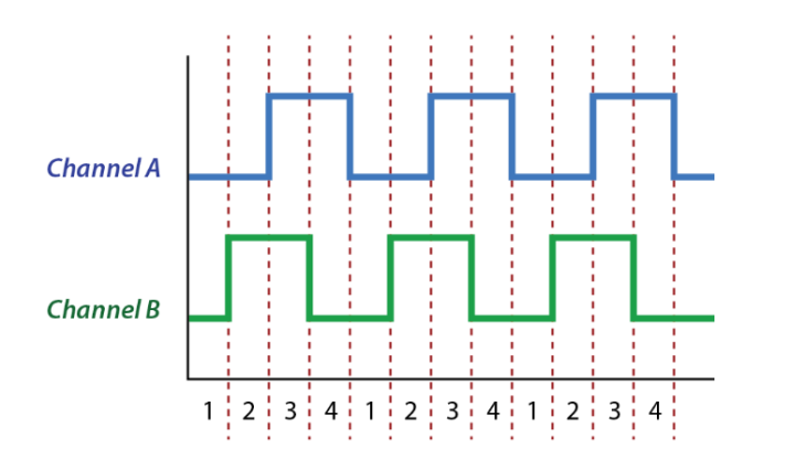
Figure 3: Phase diagram of an incremental rotary encoder. Source: Jody Dascalu
Incremental rotors generate a specified amount of pulses during one rotation of the encoder. With one signal channel, the output will look the same whether the encoder rotates clockwise or counterclockwise. With two channels, the direction of rotation can be determined by whether Channel A or B is leading. The phase difference between channels A and B indicates the direction of motion.
Quadrature
When clockwise and counterclockwise directions must be distinguished, two encoder outputs with a phase offset should be used. This is called two-bit quadrature output. As each pole pair passes by the encoder there are four unique output conditions. Further, 90° phase offset (quadrature) maximizes the margins between each state and helps to reduce errors resulting from mechanical tolerances, sensor accuracy, jitter, and noise.
Single Channel
If only one direction of rotation is being measured, an encoder with a single channel is used.
Features
Resolution
The resolution of incremental rotary encoders is the number of measuring units in a single revolution of the shaft. Resolutions are typically available up to 10,000 pulses per revolution (PPR). Higher resolutions do not necessarily improve the accuracy of the system.
The encoder’s resolution needs to be selected according to the system controller's requirements. If there is not enough resolution, it will not provide effective feedback to the controller. Incremental encoder resolution is calculated with maximum RPM and encoder operating frequency.
Positional Accuracy
The accuracy of incremental rotary encoders is the measure of error between the value that is reported by the encoder compared to the actual physical value that is measured. Accuracy is measured in arcminutes or arcseconds. High accuracy is generally 20 arcminutes or better, though there are many higher precision encoders with 5 arcseconds or better.
Programmable
Programmable rotary encoders allow users to adapt the resolution to the system's demands. This feature adds flexibility and typically helps consumers save costs. Programmable encoders are available in a variety of designs and specifications and are suitable for a wide range of applications.
Intrinsically Safe
Intrinsically safe encoders are used in hazardous areas where flammable liquids, gases, and combustible dust may be present. Some common industrial applications are oil and gas exploration, chemical production, and grain silos. Intrinsically safe encoders are used in conjunction with an energy-limiting device also known as an IS Barrier. This prevents any arcs or sparks from having enough energy to ignite hazardous materials.
Operating Temperature
For many industrial environments, the choice of incremental rotary encoder must account for environmental conditions such as humidity, the presence of moisture, and temperature. Thermal expansion of materials and components of the encoder are accounted for in encoders suitable for high temperatures. For encoders working under low temperatures, thermal contraction, and initial starting torque are considered when specifying the operating range.
Vibration and Shock Rating
Shock and vibration are common considerations for incremental rotary encoder selection as industrial environments often pose these risks. Vibration can negatively impact encoder performance and damage the device. The materials of the encoder also affect the vibration and shock rating. Some sensor engines are more susceptible to damage resulting from shock and vibrations.
For many harsh environments, magnetic encoders may be the best choice when compared to optical encoders. Magnetic encoders are noncontact and some are designed with wide air gaps making them suitable for high-vibration environments.
Related Information
Electronics360—Differential Inductive Switch Debuts
Globalspec.com—Gurley’s high-reliability rotary encoders offer accuracy and precision, solve difficult problems
- Arizona
- California
- Colorado
- Connecticut
- District of Columbia
- Florida
- Georgia
- Idaho
- Illinois
- Indiana
- Kentucky
- Massachusetts
- Michigan
- Minnesota
- Missouri
- Montana
- North Carolina
- New Hampshire
- New Jersey
- New York
- Ohio
- Oklahoma
- Oregon
- Pennsylvania
- Rhode Island
- South Carolina
- Texas
- Virginia
- Washington
- Wisconsin
- dual concentric rotary encoder
- AVR code rotary encoder
- Encoder interpolation
- incremental encoder IC
- laser rotary encoder
- miniature rotary encoder
- quadrature decoder IC
- quadrature encoder AVR
- quadrature encoder display
- quadrature encoder IC
- relative encoder
- rotary encoder coupling
- rotary encoder picbasic
- Two channel encoder
- urschel comitrol 3600
- incremental encoder pulse counter