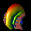
Radar and Laser Cross Section Engineering, Second Edition

As a conclusion to this chapter on time domain numerical methods, we briefly examine the transmission line matrix (TLM) method.19 ,20 In earlier chapters, equivalent transmission line circuits have been used to represent the behavior of electromagnetic fields. The TLM method is essentially an extension of this representation: voltages and currents in electrical circuits are used to simulate the propagation of waves in unbounded space. This is not a surprising development, because the analogy of free space as a TEM transmission line has been around since the early 20th century. As was the case for FEM and FDTD, the TLM method was used for several decades to analyze closed problems such as obstacles in waveguides. It has been only since the development and refinement of absorbing and transparent boundary conditions that the method has been extended to open problems (i.e., antenna radiation and scattering).21
Similar to FEM and FDTD, the computational domain must be discretized. The discretization points in space, or nodes, become junctions of transmission lines. The basic building block is a differential length ( ? x, ? y, ? z) of lumped element transmission lines in the x, y, and z directions. As illustrated in Fig. 4.44 for two dimensions, there are two types of nodes: shunt nodes used for TM z modes and series nodes for TE z modes. (There are several variations in the capacitance and inductance parameters, depending on how...