Radar and Laser Cross Section Engineering, Second Edition

Transmission lines are structures designed to guide electromagnetic waves efficiently. Potential sources of energy loss on transmission lines include attenuation, reflection, and radiation. Commonly used structures include coaxial, two-wire, and microstrip configurations. The geometry of the line, its dimensions, and the materials of which it is composed determine its characteristic impedance ( Z 0), phase velocity ( u p), and attenuation constant ( ?). These are the three quantities that primarily determine the line s electrical performance.
In practice, the behavior of electromagnetic waves guided by a wide range of objects can be modeled with a transmission-line representation. For instance, at certain angles, a flat conducting plate will capture energy from a plane wave and guide the wave along its surface. This is a traveling wave, and its behavior can be modeled by an equivalent transmission line with the appropriate length, impedance, attenuation constant, and phase velocity. This allows use of the standard equations for impedance transformations and matching to design networks to control reflections and radiation.
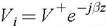
Figure D.1 shows a uniform finite-length transmission line with a characteristic impedance Z 0 and load Z L. Uniform implies that the geometry and materials are independent of length. Using the coordinate system in the figure, a wave launched at the generator side travels down the line in the + z direction
where ? is the phase constant of the line (lossless line assumed: ? = 0). If the