Gas Well Testing Handbook
Offering a thorough understanding of gas well test analysis basics, this book focuses on practical field application, where over 100 field examples are presented to illustrate basic methods for analysis.
 TABLE OF CONTENTS
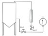
 The natural gas is measured by volume in standard cubic feet at an operating pressure and temperature and is corrected to some reference or base pressure and temperature, generally 60 F and atmospheric pressure. The two most commonly used gas measurement devices are the orifice meters and critical flow provers.
An orifice meter is utilized for gas measurement if environmental constraints prohibit gas venting to the atmosphere. A typical closed-orifice metering system consists of orifice plates, meter tubes, flange taps, and pipe taps. The gas flow rate through a closed-orifice metering system is determined using

where

The term C ? is known as the orifice constant, the value of which depends primarily on the basic orifice factor, F b. Values for most of these constants are tabulated for various orifice sizes and flowing conditions in Tables D 1 and D 2. The F b F Pb F tb F g F tf F r F Pv F m Y factors are determined empirically and are periodically updated by the AGA.
| 2-inch prover orifice diameter (inch) | 2-inch prover factor F p (mscfd) | 4-inch prover orifice diameter (inch) | 4-inch prover factor F p (mscfd) |
|---|---|---|---|
| 1/16 | 0.06560 | 1/4 | 1.74 |
| 3/32 | 0.1446 | 3/8 | 2.414 |