E.1 Scattering Parameters
At microwave frequencies, direct measurement of voltage and current is difficult, if not impossible. Furthermore, as in the case of waveguides, voltages and currents are not unique. Scattering parameters are one of several means of characterizing devices based on incident and scattered voltage waves (i.e., electric field). Other methods are Z parameters, Y parameters, and ABCD parameters. One advantage of scattering parameters is that they are easily measured.
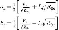
Figure E.1 shows an N -port device. At each port, there is an incident and scattered wave, denoted by a n and b n , respectively. These are related to the true voltage and current by
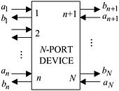 Fig. E.1: N-port device with incoming and outgoing waves.
 These are normalized waves due to the presence of R 0, a real normalizing constant that is arbitrary but that is usually chosen to be the impedance of the line (or generator) feeding the device. The normalized voltage and current at port n are
or,
Traditionally, a and b have been referred to as voltage or current waves, even though their unit is  . Frequently
  and
and  are used in place of a n and b n.
Generalized scattering parameters allow the impedance viewed at each port to be different, for example, as in the case of an impedance transformer. However, most devices are designed to have the same input impedance at all ports, and this is the case...