Electromagnetics for High-Speed Analog and Digital Communication Circuits

9.6: Lossy Transmission Lines

9.6 Lossy Transmission Lines

We can account for loss in a transmission line by working directly with Eqs. (9.27) and (9.28). In particular, all the calculation of the previous section can be redone to yield similar expressions.

Transmission line input impedance

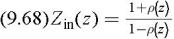
Taking the ratio of voltage to current on the transmission line, we have the general expression


Using the definition of the reflection position, ?( z ), we have


which can be written explicitly in terms of the load impedance


It s easy to show that the above equation degenerates to Eq. (9.5) under the lossless case.

Example 17

Calculate the input impedance of a short-circuited transmission line of length ? at low frequency. Assume the line is very short, e.g. ? ? ? 0.

From Eq. (9.6), substituting Z L = 0, we have


Recalling the definition of ? and Z 0, we have


where R T is the resistance of the line and L T is the inductance of the line. Thus a shorted short transmission line behaves like a lumped inductor.

Dispersionless line

In general, a lossy transmission line introduces distortion due to dispersion. Dispersion occurs when the propagation speed and attenuation is frequency dependent. If a group of frequencies are excited along the line, they travel along the line with different velocity and experience different attenuation. Thus, if an arbitrary waveform (say a pulse) is excited on the line, after significant propagation it will arrive with a completely...

UNLIMITED FREE
ACCESS
TO THE WORLD'S BEST IDEAS

SUBMIT
Already a GlobalSpec user? Log in.

This is embarrasing...

An error occurred while processing the form. Please try again in a few minutes.

Customize Your GlobalSpec Experience

Category: Specialty Optical Fiber
Finish!
Privacy Policy

This is embarrasing...

An error occurred while processing the form. Please try again in a few minutes.