Electromagnetics for High-Speed Analog and Digital Communication Circuits

9.11: Transmission Line-Matching Networks

9.11 Transmission Line-Matching Networks

Matching with lumped elements

Recall the input impedance looking into a T-line varies periodically


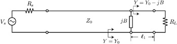
As shown in Fig. 9.36, move a distance ? 1 away from the load such that the real part of Z in has the desired value. Then place a shunt or series impedance on the T-line to obtain the desired reactive part of the input impedance (e.g. zero reactance for a real match). For instance, for a shunt match, the input admittance looking into the line is


Figure 9.36: A section of transmission line and a shunt reactance can be used to match a load to a desired impedance.

At a distance ? 1, we desire the normalized admittance to be y 1 = 1 ? jb. Substitute ? L = ?e j ? and solve for ? 1 and let ? = 2 ?z + ?


Solve for ? (and then ? 1) from ( y) = 1


At ? 1, the imaginary part of the input admittance is


Placing a reactance of value ? b in shunt provides impedance match at this particular frequency. If the location of ? 1 is not convenient, we can achieve the same result by moving back a multiple of ?/2.

Matching with T-line stubs

At high frequencies the matching technique discussed above is difficult due to the lack of lumped passive elements (inductors and capacitors). But...

UNLIMITED FREE
ACCESS
TO THE WORLD'S BEST IDEAS

SUBMIT
Already a GlobalSpec user? Log in.

This is embarrasing...

An error occurred while processing the form. Please try again in a few minutes.

Customize Your GlobalSpec Experience

Category: Impedance Matching Networks
Finish!
Privacy Policy

This is embarrasing...

An error occurred while processing the form. Please try again in a few minutes.