More Practical Filters and Couplers: A Collection from Applied Microwave & Wireless
With additional articles on filter and coupler design, this collection focuses on tunable structures and couplers.
 TABLE OF CONTENTS
 The authors describe a method for building cavity filters with minimal loss and temperature variations suitable for satellite and other critical filter applications
By Michael E.Bizal and John E.Mulholland
From APPLIED MICROWAVE & WIRELESS, VOL. 3, NO. 3, FALL 1991
Microwave filters are central to a wide variety of communications system design problems, since the available spectrum becomes increasingly crowded by more and more users. Filters are the means to confine the radiation from high-power transmitters within assigned spectral limits, or to protect receivers from interference outside of their operating frequency bands. This article describes space qualified X-band filters, comprising the majority of RF filtering for the transponders of the communications satellites built by GE.
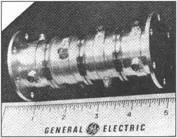
Figure 1 shows a typical filter composed of a stack of cylindrical cavities, machined from a low thermal expansion alloy, Invar . The cavities are coupled to each other via small irises in their common end walls. The cavities are permanently joined by laser welding after passing pre-weld testing in a threaded rod test fixture.
Typical specifications require a bandwidth of about 1 percent in the 8 GHz frequency range, a 30 dB rejection bandwidth of 1.2 times the operating bandwidth, maximum center frequency insertion loss of 1.5 dB, maximum peak-to-peak ripple of 0.2 dB, minimum pass-band return loss of 18 dB, and maximum pass-band group delay of 25 nanoseconds.
This performance is required over the specified temperature range of ?34 to +71 degrees Celsius.