More Practical Filters and Couplers: A Collection from Applied Microwave & Wireless

With additional articles on filter and coupler design, this collection focuses on tunable structures and couplers.
 TABLE OF CONTENTS
 To select an optimum filter network, a trade-off study of electrical parameters such as bandwidth and insertion loss is made. For the specifications described, direct-coupled cylindrical cavities with inductive irises using the TE111 mode proved to be the best choice, since these cavities offer a large unloaded Q for low insertion loss. Good mode separation is achieved with this choice of cavity, which is only slightly larger than some of the lower Q alternatives shown in Figure 2 [4]. Other structures were considered, but since a sharp rejection slope is required, the structure having the highest unloaded Q for the smallest size was the end coupled cylindrical cavity.
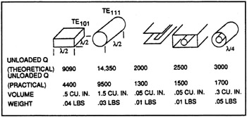
All of the basic filter design theory employed for the filters described in this article was adapted from Microwave Filters, Impedance-Matching Networks and Coupling Structures by Matthaei, Young and Jones [10]. All subsequent chapter references are to this text.
The filter is designed and optimized using a set of in house computer programs. The first, called BPFTR (band-pass filter trade-off routine) [6], is based upon a transfer function analysis of the pole-zero locations of a lossless low-pass prototype network, consisting of series inductances and shunt capacitances. The routine follows the approach given in Chapter 4.
The process that we use to find the element values is inverted from the customary analysis. That is, given the frequency characteristics of the transfer function, the program iterates the number...



