More Practical Filters and Couplers: A Collection from Applied Microwave & Wireless

With additional articles on filter and coupler design, this collection focuses on tunable structures and couplers.
 TABLE OF CONTENTS
 Another factor considered is how the coupling between adjacent and non-adjacent cavities changes as a result of the mechanical tolerance of the coupling irises (holes). Figure 8 shows the sensitivity of iris coupling values to a change in iris dimensions for a typical 8-pole, 4-cavity dual mode filter [2]. The coupled cavity model of the filter is shown in Figure 8, with the individual cavities numbered and the iris coupling between cavities indicated at cavity boundaries. M1 and M2 denote the major iris axis and minor iris axis coupling values, respectively, with the major iris axis providing the larger coupling.
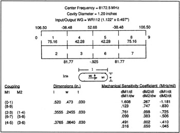
The minor axis provides the coupling between nonadjacent resonators. The negative sign for minor axis coupling indicates that the sense of the field in the two cavities must be opposite. The coupling values not shown at a cavity boundary represent the coupling of the two orthogonal modes within each cavity.
The dimensions of each iris are shown in the figure and the change in major or minor coupling in MHz is shown for a one mil (0.110 ) variation in each dimension. The results indicate that the iris coupling changes typically between 1 percent and 1.5 percent for a one mil change in iris size.
The mechanical tolerance of the iris dimensions for production units was...