More Practical Filters and Couplers: A Collection from Applied Microwave & Wireless

With additional articles on filter and coupler design, this collection focuses on tunable structures and couplers.
 TABLE OF CONTENTS
 This balun design allows impedance transformation in addition to providing the balanced-to-unbalanced function
By Jeff Merrill
From APPLIED MICROWAVE & WIRELESS, VOL. 12, NO. 4, APRIL 2000
This article introduces a technique for designing balanced to unbalanced transmission line transformers (baluns), which offer the flexibility to transform impedance from the balanced to unbalanced ports. This device has applications in the RF/microwave industry for antennas, push-pull amplifiers, mixers and modulators, as well as other circuits. Two backward-wave couplers with a specific interconnect and port termination scheme are used to achieve this balun function.
The discussion that follows assumes the reader is familiar with the concepts of characteristic impedance and even and odd mode impedances as they relate to backward-wave couplers [1, 2]. The schematic shown in Figure 1 illustrates the interconnect scheme for the balun. To help simplify the analysis, this illustration intentionally omits parasitic elements that are due to interconnection or packaging. These issues must be given serious consideration when implementing this design into a packaged product. However, because the parasitics associated with physical implementation will vary depending on the type of structure that is used, these issues will not be addressed here and are left for the reader to consider in his or her specific design.
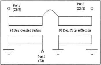
Figure 1 shows a circuit is composed of two equivalent couplers which both have a characteristic impedance of Z 0. After shorting three of the ports and making the coupler interconnection,...