More Practical Filters and Couplers: A Collection from Applied Microwave & Wireless
With additional articles on filter and coupler design, this collection focuses on tunable structures and couplers.
 TABLE OF CONTENTS
 By Samuel J.Parisi
From APPLIED MICROWAVE & WIRELESS, VOL. 1, NO. 2, AUGUST/SEPTEMBER 1989
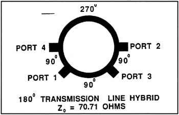
Figure 1 shows a conventional 180 degree, 3 dB transmission line hybrid, often called a rat-race coupler or a ring hybrid, together with its electrical characteristics normalized to a 1-hertz center frequency. Due to symmetry, the return loss behavior of ports 3 and 4 are not shown. This abbreviated presentational procedure will be used throughout the paper. At frequencies below 18 GHz, this hybrid occupies much more area than an equivalent lumped-element design. For example, a 70.7 ohm, quarter wavelength transmission line on a 100 micrometers thick GaAs substrate at 8 GHz is 3328 micrometers in length. When realized in ring form, it occupies approximately 32 square millimeters in this medium. An electrically equivalent design (at the center frequency) in lumped element form occupies only about 1 square millimeter, an area savings of over 96 percent, i.e., a reduction in area by a factor of 30!
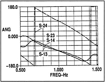
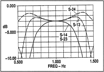
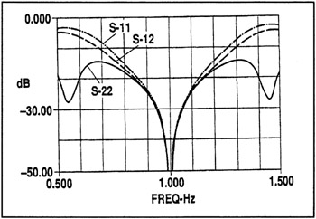
Nor is the lumped approach only useful to reduce the occupied area of couplers in MMIC circuits. The same methods can be employed to shrink coupler sizes in stripline or microstrip, particularly below 1 GHz, for which frequencies the wavelength, even in dielectric, can exceed 1 foot.
This design is based on deriving equivalent pi ...