More Practical Filters and Couplers: A Collection from Applied Microwave & Wireless
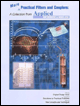
With additional articles on filter and coupler design, this collection focuses on tunable structures and couplers.
 TABLE OF CONTENTS
 Following the final alignment and test the filters were subjected to two non-operational thermal cycles consisting of temperature plateaus of ?40 and +85 degrees Celsius. An operating cycle consisting of temperature plateaus of ?34 and +71 degrees Celsius followed the non-operating cycles. Test results indicated a worst case shift of frequency for any cavity of 1.0 MHz and was approximately 0.7 MHz on average, with the greatest shift occurring at the cold extreme [2]. This is noteworthy, since a cavity can easily be tuned to within 0.1 MHz of the desired value so that, on average, the combination of initial tuning error and temperature effects will result in less than a 1 MHz total shift but the design allows for a total shift of 2.0 MHz [2].
The variation in coupling values during the thermal test proved negligible over the temperature extremes. This is due to the scaling effect of the irises and cavities changing in proportion [2]. In the case of those coupling values provided by tuning screws, however, a change of about +0.4 percent was noted with the coupling, decreasing at the cold extreme and increasing at the hot extreme. This is due primarily to a shrinkage and expansion of the brass tuning screw but does not pose a problem since these values can be set closely to the design values and a change in coupling magnitude of +0.4 percent is well within the coupling tolerance [2].
Following the thermal test and a...