More Practical Filters and Couplers: A Collection from Applied Microwave & Wireless

With additional articles on filter and coupler design, this collection focuses on tunable structures and couplers.
 TABLE OF CONTENTS
 Initially the cavities were machined in cylindrical halves from solid billets of Invar, being ground and polished internally to a finish of better than 8 microinches. Coupling holes are bored with a tolerance of 0.0005 inch, allowing an extra 0.0005 inch increase in diameter to allow for the subsequent silver plating, which has a thickness of 0.0001 to 0.0002 inches. Male-female joints at the cylinder halves have the plating removed and are laser welded to complete the individual resonators.
The resonators were jigged together using thread rods to hold the complete filter together for electrical testing. Reject cavities were retuned and reworked as necessary, and then the complete filter was welded together. Each cavity has a thicker ring where the laser weld is made and the tuning screws inserted. The iris thickness between cavities is 0.020 inch and the wall thickness between thick rings is 0.016 inch. Figure 9 illustrates the cavity section design prior to welding.
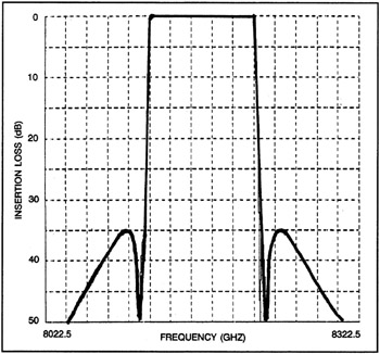
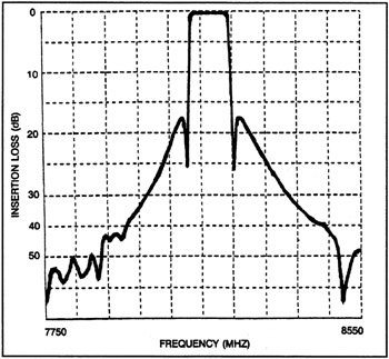
The calculated performance of the filter (Figure 10a) was in agreement with that measured (Figure 10b). This design and fabrication process was effective in the production of a large number of filters in one phase of a communications satellite production contract, but an improved method, the cylinder and plate technique, proved more practical. In this design technique, the iris is a separate flat plate sandwiched between two cylinders (see Figure 11).