Principles of Turbomachinery in Air-Breathing Engines
Figure 3.5 shows one of the most general turbine sections. The flow stream in this figure progresses from a radial stage to an axial stage and finally through a stationary cascade of exit guide vanes. The T- s diagram in the same figure highlights a very important fact: Regardless of the component shape, and whether or not it is associated with shaft work, only one variable, namely ? s, is both loss-related and addable. It is therefore only sensible to devise an entropy-production-based loss coefficient that, by reference to Figure 3.5, is as capable of representing the overall multistage flow process as it is when applied to a single component in the flow path. This rather universal loss coefficient is referred to by the symbol q, where
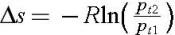
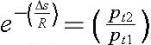
In an adiabatic flow process, across a stationary component, the loss coefficient q is identical to the traditional total pressure loss coefficient, ? . The latter is simply defined as the total pressure loss, ? p t, divided by the inlet total pressure, p t 1. Noting that the total temperature in this case remains constant, we can prove the equality of ? and q by recasting the entropy-production expression as
which means that
or
Tracking the sequence of events on the T- s diagram in Figure 3.5, the path of the process is continually shifting to the right, as would be expected. The entropy rise in...