Principles of Turbomachinery in Air-Breathing Engines

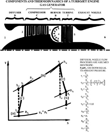
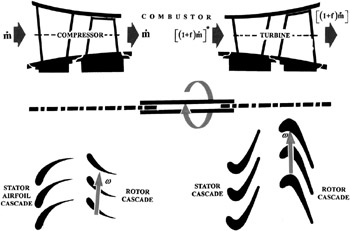
Consider the simple nonafterburning, single-spool turbojet engine, which is shown schematically in Figure 12.1. Assuming a viable (i.e., stable compressor) operation mode, there are obvious constraints relating the gas-generator components to one another. These generally enforce the uniformity of shaft speed as well as ensure the mass- and energy-conservation principles (Fig. 12.2). In terms of physical variables, these can be expressed as follows:
where f is the fuel-to-air ratio and ? m is the torque-transfer mechanical efficiency, with the subscripts T and C referring to the turbine and compressor sections, respectively. The mechanical efficiency ? m in equation (12.3) accounts for such contributors as the shaft length and the bearings effect on the shaft.
The basic problem at hand, by reference to Figure 12.3, is to be able to find the thermophysical state T, on the turbine map, once the corresponding state C is placed on the compressor map, or vice versa. To this end, it is assumed that the so-called pumping characteristics, primarily represented by the compressor and turbine maps, of the gas generator are given. In addition to the maps, these normally include a burner (or combustor) chart. The chart will provide, among other variables, the total pressure loss across this component. The loss in this case is a function...