Principles of Turbomachinery in Air-Breathing Engines

Figure 4.1 shows a general-type mixed-flow compressor rotor. The thermophysical states 1 and 2 represent average conditions over the entire inlet and exit stations, respectively. With the rotor blade-to-blade hub-to-casing passage being the control volume, and with the continuity and energy equations (already covered in Chapter 3), we are now left with the momentum-conservation principle to implement.
The momentum equation is a vector relationship that can be resolved in the z, r, and ? coordinate directions. In the following, these three (scalar) relationships will be cast and their kinetic consequences discussed.
Axial-momentum equation:
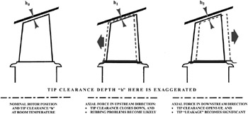
The axial force F z will be absorbed, in part, by a thrust bearing in most cases. Nevertheless, part of this force can be mechanically and/or aerodynamically damaging. Referring to Figure 4.2, for an axial-flow turbine rotor, the rotating blades will indeed move axially in response to this force.
Figure 4.2 shows the two different scenarios when a net axial force exists on the rotor blades. Movement to the left in this figure would close down the tip-to-casing clearance gap. Knowing that this clearance is normally less than 0.5 mm, particularly in high-pressure turbines, it is perhaps obvious that this rotor displacement can very well lead to the blades rubbing against the casing, potentially causing a catastrophic mechanical failure. Referring to the other rotor-displacement scenario in Figure 4.2, the rotor displacement to the...