Principles of Turbomachinery in Air-Breathing Engines

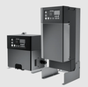
For more than three decades now, radial-inflow turbines have been established as a viable alternative to its axial-flow counterpart, specifically in power-system applications. Despite its relatively-primitive means of fabrication, radial turbines are capable of extracting a large per-stage shaft work in situations with low mass-flow rates. This turbine category also offers little sensitivity to tip clearances, in contrast to axial-flow turbines. Nevertheless, the turbine large envelope, bulkiness and heavy weight (Fig. 10.1), virtually prohibits its use in propulsion devices.
Figure 10.2 shows the velocity diagrams at the rotor inlet and exit stations within a typical radial-turbine stage. As derived in Chapter 4, the combined Euler/energy-transfer equation can be expressed, for the specific shaft work ( w s), as
where the subscripts 1 and 2 m refer to the rotor inlet and mean-radius exit stations, respectively. The velocity components in expression (10.1) are all shown in Figure 10.2.
For all three terms in expression 10.1 to contribute positively to the shaft-work production, the following velocity-component relationships must be satisfied:
This implies a streamwise decline in radius across the rotor. It also underscores the use of the phrase inflow in referring to this turbine category.
This implies an accelerating (nozzle-like) blade-to-blade passage, as shown in Fig. 10.2.
This condition calls for a large stator-exit velocity (Fig. 10.2) or, equivalently, a large stator-exit swirl angle ( ?