Writing Testbenches using SystemVerilog

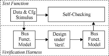
A testbench need not be a monolithic block. Although Figure 1-1 shows the testbench as a large thing that surrounds the design under verification, it need not be implemented that way. The design is also shown in a single block, and it is surely not implemented as a single unit. Why should the testbench be any different? Figure 6-1 depicts the architecture of a generic testbench. In this chapter, I will describe how to implement each component.
| Note | The previous chapter was about low-level testbench components. |
In Chapter 5, we focused on the stimulus and monitoring of the low-level signals going into and coming out of the device under verification. I showed how to abstract them into transactions using bus-functional models. The emphasis was on the stimulus and response of interfaces and the need for managing separate execution threads underneath a useful transaction-level interface. If you prefer a bottom-up approach to writing testbenches, I suggest you start with the previous chapter.
| Note | This chapter focuses on the structure of the testbench. |
This chapter concentrates on implementing the many testcases and filling the functional coverage models that were identified in your verification plan. I show how best to structure the bus-functional models into a transaction-level verification harness. This verification harness will create the platform on top of which the self-checking structure and stimulus sources will be built. I also describe how to create random generators that can be constrained easily, with a minimum of modifications,...