High Voltage Capacitors Information
Last revised: October 17, 2024
Reviewed by: Scott Orlosky, consulting engineer
High voltage capacitors are passive electronic components that store charge and energy for use in high voltage applications. They consist of two conducting plates separated by an insulating material called the dielectric.
Types
 Film capacitors are high voltage capacitors made out of plastic. There are two basic types:
- Film-foil capacitors include one or more layers of a plastic film dielectric wound alternately with metal foil electrodes.
- Metallized film capacitors consist of a film dielectric on which the metal electrode has been vapor-deposited. The layers are wound into a convoluted roll so that the electrodes extend beyond the dielectric films.
Capacitance, a measure of energy storage ability, is typically expressed as:

- A is the area of the electrodes.
- D is their separation.
- K is a function of the dielectric between the electrodes.
Selecting High Voltage Capacitors
Selecting high voltage capacitors requires an analysis of dielectric materials. Dielectrics are poor conductors since they don’t have a lot of free electrons. However they are good at storing electrostatic fields.
- Aluminum electrolytic capacitors are polar devices that feature a high volumetric density but cannot withstand reverse voltages.
- Ceramic capacitors are made of resistive ceramic materials and provide bonded metal contacts. Examples include ceramic Z5U, a Class III ceramic dielectric, and ceramic X7R, a temperature-stable material that is suitable for bypassing and coupling applications.
- Glass, mica, oil, air, and paraffin paper are other commonly used dielectric materials.
- Polycarbonate, polypropylene, and polystyrene are suitable for applications such as fillers and timers.
- Tantalum is a metallic element, is used to make a variety of alloys.
- Niobium is a hard ceramic material characterized by high conductivity, has similar chemical properties to tantalum.
Performance Specifications
 Performance specifications for high voltage capacitors include capacitance range and capacitance tolerance, a percentage of total capacitance. Working DC voltage, insulation resistance, dissipation factor, and temperature coefficient are additional considerations.
- Working DC voltage (WVDC) is the maximum voltage that can be applied continuously at any temperature between a lower category temperature and the rated temperature.
- Insulation resistance is the ratio between an applied DC voltage and the resulting leakage current.
- Dissipation factor (DF) is the ratio between the resistive and reactive parts of a capacitor’s impedance when a sinusoidal voltage at a specified frequency is applied.
- Temperature coefficient is the change in capacitance measured over a range of temperatures.
Mount Types
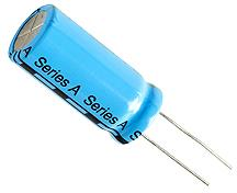
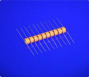
High voltage capacitors can use axial, radial, flying, tab, screw, gull wing, or J-leads. Some devices bolt into place while others require or include mounting brackets. Pole-mounted capacitors are also available.
- Surface mount technology (SMT) is one of two standard means to attach high voltage capacitors to a printed circuit board (PCB). The capacitors are placed so that they are touching small conductive landing pads which have been coated with solder paste and are part of the circuit. They are then heated above the solder melting point so the solder will flow due to capillary action and create a strong, conductive bond to the capacitor.
- Through hole technology (THT) mounts components on a PCB by inserting component leads through holes in the board and then soldering the leads in place on the opposite side of the board.
Package Types
 High voltage capacitors are packaged in tape reels, trays or rails, shipping tubes or stick magazines, and in bulk packs. Tape reel assemblies include a carrier tape with embossed cavities for storing individual components.
A cover tape seals the carrier tape in place and the composite tape is wound on a reel that can be loaded into industry-standard, pick-and-place board assembly equipment.
High voltage capacitors with leads on four sides are often packed in trays or rails that are made of carbon-powder or fiber materials and molded into rectangular outlines that contain matrices of uniformly spaced pockets.
Shipping tubes or stick magazines are containers made of rigid polyvinylchloride (PVC) and extruded in industry-standard sizes. Bulk packs are used to distribute components as individual parts.
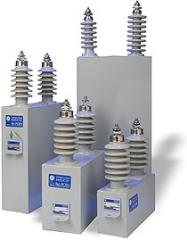
Capacitor Banks
A common use for high voltage capacitors is to improve the efficiency of AC power systems. They will often be arranged in “banks” of multiple capacitors depending on the load. These capacitor banks need to be protected from overloads so they usually have specialty fuses either one per capacitor (individual protection) or placed to protect the entire bank (group protection). Since these are high voltage devices there are specific standards for the fuses used for this function.
Standards
BS EN 60549 — High-voltage fuses for the external protection of shunt capacitors.
IEC 60549 — High-voltage fuses for the external protection of shunt capacitors.
IEEE C37.43 — Standard specifications for high-voltage expulsion, current-limiting, and combination-type distribution and power class external fuses, with rated voltages from 1 kv through 38 kv, used for the protection of shunt capacitors.
High Voltage Capacitor FAQs
What are the typical applications of high voltage capacitors?
High voltage capacitors are used in various applications including:
- Critical timing and tuning circuits
- Circuits requiring low loss
- Circuits with pulse and high current
- Switch-mode power supplies
- High-voltage coupling
- DC blocking
- Voltage multiplier circuits
- Extreme environments such as down-hole exploration, aerospace engine compartments, and geophysical probes
What are the temperature capabilities of high voltage capacitors?
Some high voltage capacitors, such as the HV-HT capacitors developed under KEMET’s platform, are capable of operating at temperatures up to 200° C.
What are the advantages and disadvantages of different dielectric materials used in high voltage capacitors?
- Ceramic is good for high voltage applications but may have low temperature stability and hazardous dielectric heating in RF applications.
- Mica is durable with excellent temperature stability but it is susceptible to moisture and high cost.
- Glass is reliable and stable with excellent radiation resistance but also expensive.
- Polymer is suitable for a variety of applications including high voltage and RF, but may have relatively low temperature resistance and can be easily damaged by pulses or transients.
- Electrolytic material has high capacitance to volume ratio, stable, reliable, and durable but may violently explode or burst when overloaded.
What are some critical factors to consider when designing with high voltage capacitors?
When designing with high voltage capacitors, factors such as creepage and clearance are critical, especially for connectors and cables. Clearance is the shortest distance, in air, between two conductors. While creepage is the shortest distance along the surface of an insulating material between two conductive parts. These factors are essential to ensure the safety and reliability of the high voltage interconnects.
What are some important details about the dissipation factor?
The dissipation factor is a critical parameter in evaluating the performance of capacitors, especially high voltage capacitors. Here are the key points to understand:
Mathematically, the dissipation factor (DF) can be expressed as:
DF = Rs/Xc where (Rs) is the equivalent series resistance and (Xc) is the capacitive reactance.
The dissipation factor is an indicator of the energy losses within the capacitor. A lower dissipation factor signifies lower energy losses and higher efficiency, which is particularly important in high-frequency and high-voltage applications.
The dissipation factor is typically measured using a bridge circuit or an LCR meter (L = Inductance; C=Capacitance; R = Resistance) at a specified frequency. The frequency at which the measurement is taken can significantly affect the DF value.
High dissipation factors can lead to increased heat generation within the capacitor, which may affect its reliability and lifespan. Therefore, capacitors with low DF are preferred for applications requiring high efficiency and stability.
The dissipation factor varies with the dielectric material used in the capacitor. For instance, ceramic capacitors generally have a low DF, making them suitable for high-frequency applications, whereas electrolytic capacitors may have a higher DF.
The dissipation factor can change with temperature. Capacitors designed for high-temperature environments, such as the HV-HT capacitors capable of operating up to 200° C, need to maintain a low DF to ensure reliable performance.
The dissipation factor is a vital parameter that affects the efficiency and reliability of high voltage capacitors. By understanding and optimizing the DF, engineers can ensure that capacitors perform effectively in their intended applications.
What are the typical values of dissipation factor for different types of capacitors?
Typical dissipation factor values for different capacitor types include
Ceramic capacitors
Generally, ceramic capacitors have a low dissipation factor, making them suitable for high-frequency applications. The DF can be as low as 0.1% to 1% depending on the specific type of ceramic material used.
Mica capacitors
Mica capacitors are known for their excellent temperature stability and low dissipation factor, typically in the range of 0.01% to 0.1%.
Glass capacitors
Similar to mica capacitors, glass capacitors also exhibit a low dissipation factor, usually around 0.1% to 0.5%.
Polymer capacitors
Polymer capacitors, including polystyrene, polycarbonate, polyamide, polypropylene (PP), and polyester, have a moderate dissipation factor. The DF can range from 0.1% to 2% depending on the specific polymer material.
Electrolytic capacitors Electrolytic capacitors, such as aluminum and tantalum electrolytic capacitors, generally have a higher dissipation factor compared to other types. The DF can range from 1% to 20% or higher, depending on the specific construction and application.
These values provide a general guideline, but the exact dissipation factor can vary based on the specific design and manufacturing process of the capacitor.
High Voltage Capacitor Media Gallery
References
Electronics360—High-Voltage Capacitors Are Good to 200° C
GlobalSpec—Capacitors
Image Credits:
Morgan Advanced Materials | GE Digital Energy
- Axial Leads
- Bolt Mounted
- Bulk Pack
- Ceramic
- Ceramic COG (NPO)
- Ceramic X7R
- Film Capacitors
- J-Leads
- Metallized Dielectric
- Military Standards
- Monolithic / Single Layer
- Multilayer
- Paraffin Paper
- Polyester
- Polypropylene
- Radial Leads
- RoHS Compliant
- Self-healing
- Surface Mount Technology (SMT)
- Surface Mount Technology (SMT)
- Tantalum Oxide
- Tape Reel
- Teflon®
- Through Hole Technology (THT)
- Tray / Rail
- Wound