Chip Capacitors Information
Last revised: September 24, 2024
Reviewed by: Scott Orlosky, consulting engineer
Chip capacitors are passive integrated circuit (IC) components that store electrical energy. Chip capacitors are simply capacitors manufactured as integrated circuit (IC) devices, also known as chips or microchips. They are typically square or rectangular, with the length and width of the device determining its power rating. Chip capacitors typically do not have leads and mount directly onto a printed circuit board (PCB), and are therefore considered surface mount (SMT) products.
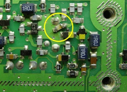
A circuit board with mounted SMD components. A chip capacitor is highlighted at top center. Image credit: ham-radio.com
The following images describe the manufacturing of multi-layer ceramic chip capacitors (MLCC).
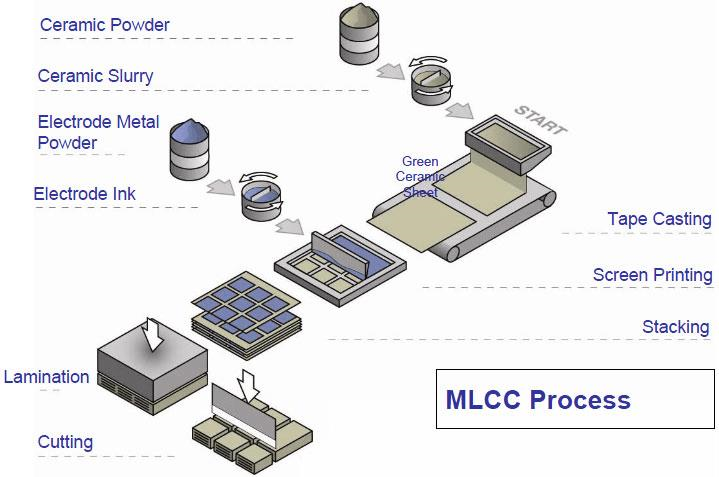
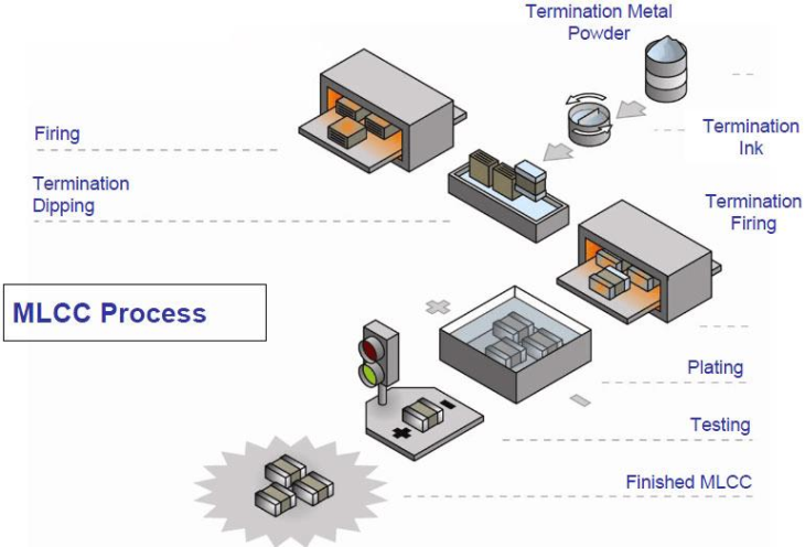
Initial (top) and final stages of chip capacitor manufacturing. Image credit: Johnson Dielectrics
Package Standards
Rectangular surface mount components, such as chip capacitors, are sometimes referred to by standard metric or imperial codes. These codes are listed below, first in imperial size with metric code in parentheses, then nominal metric dimensions. Note the direct correlation between the metric code and nominal size.
- 01005 (0402): 0.4 x 0.2 mm
- 0201 (0603): 0.6 x 0.3 mm
- 0402 (1005): 1 x 0.5 mm
- 0603 (1608): 1.6 x 0.8 mm
- 0805 (2012): 2 x 1.25 mm
- 1008 (2520): 2.5 x 2 mm
- 1206 (3216): 3.2 x 1.6 mm
- 1210 (3225): 3.2 x 2.5 mm
- 1806 (4516): 4.5 x 1.6 mm
- 1812 (4532): 4.5 x 3.2 mm
- 2010 (5025): 5 x 2.5 mm
- 2512 (6432): 6.4 x 3.2 mm
- 2920: 7.4 x 5.1 mm
- Tantalum chip capacitor dimensions are specifically standardized by the Electronic Industries Alliance (EIA) and are based in part on metric codes, with an added code for maximum device height. For example, the nominal dimensions of an EIA 2920 capacitor are 7.4 mm x 5.1 mm.
Specifications
Packing Method
Chip capacitors, like many other small electronic components, may be packed in tape reels, trays, or shipping tubes. All three methods provide compatibility with standard pick-and-place machines and other assembly equipment.
Tape reels consist of carrier tape with embossed cavities for individual components. After components are mounted on the tape, a cover tape seals the devices and the carrier tape is wound onto a reel. Tape and reel assemblies provide the advantage of component isolation. Tape is well-suited to SMT components.
Trays (or rails) are molded into rectangular outlines containing uniformly spaced pockets for storing components. Trays are typically used to pack and ship components with leads, and are stacked and bound together to facilitate shipping and handling.
Shipping tubes are rigid PVC containers that protect components during shipping and provide proper component orientation and positioning.
Dielectric Type
A capacitor's attributes, as well as capacitance, are heavily influenced by the dielectric (insulating) material between the device's plates. Typical dielectric materials can be classified into three general groups: film, electrostatic, and electrolytic.
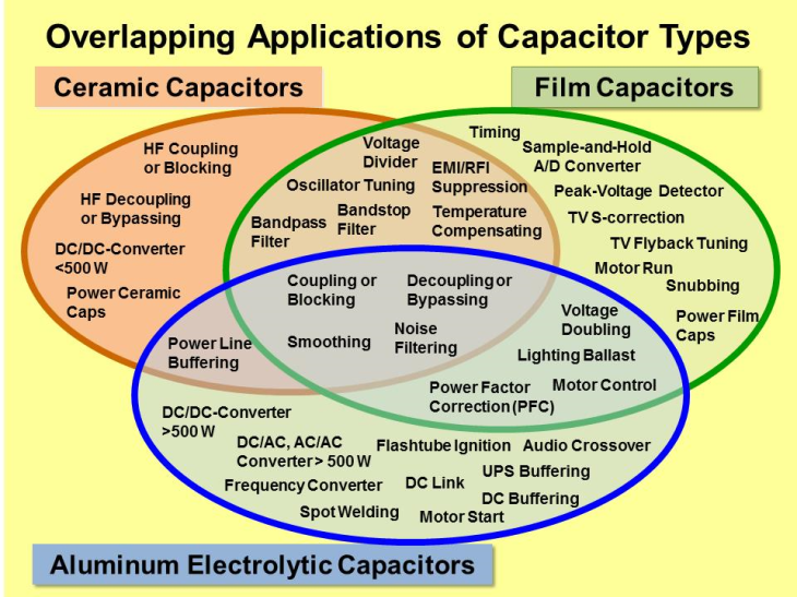
Capacitor applications by type. Image credit: Elcap
Film capacitors feature thin plastic film as a dielectric, and may be metallized, meaning that metal electrodes are previously vapor-deposited on the film. Common film capacitor materials include polyester, polypropylene, and polystyrene. Film capacitors are excellent general-purpose devices with high dielectric strengths, low moisture absorption, and high insulation resistance. Capacitors with single-layer dielectrics have slightly poorer temperature stability and resistance, while multi-layer dielectrics enable smaller device sizes and improved temperature stability.
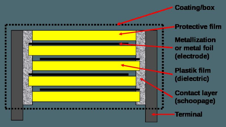
Cross-section of a typical film capacitor. Image credit: Elcap
Electrostatic capacitors feature dielectric materials that naturally support an electrostatic field — which is crucial to the device's energy-storing function — and do not conduct electrical current. These devices may use a number of different dielectric materials, which are listed below along with their attributes or typical applications.
- Air — high voltage applications.
- Ceramic — excellent for use in timing applications. Depending on the specific ceramic material, may exhibit relatively high capacitance deviation over a wide temperature range.
- Glass — high voltage applications. Very stable, reliable, and resistant to radiation.
- Mica — highly stable, good temperature coefficient, excellent endurance and reliability.
- Oil — suitable for DC applications. Oil dielectrics often require maintenance and may need to be larger than other devices to suit their intended use.
- Electrolytic capacitors feature one plate comprised of a liquid electrolyte to achieve greater capacitance using a small package. Some electrolytic capacitors may be capable of several farads of capacitance.
Standards
Chip capacitors may be subject to different standards, many of which are developed and published by the Electronic Industries Alliance (EIA). Common chip capacitor standards include:
- EIA CB 11 — Surface mounting of MLCC
- EIA IS 36 — Multilayer Ceramic Chip Capacitors
- EIA/ECA-956 — Aluminum Electrolytic Chip Capacitors
Chip Capacitors FAQs
What are the benefits of using surface mount (SMT) chip capacitors?
Surface mount chip capacitors do not have leads and are designed to mount directly onto a PCB. They are generally smaller, cheaper to manufacture, and easier to handle with standardized automation equipment compared to their leaded counterparts.
What are some specific models of chip capacitors and their features?
Different models among the stacked capacitors series have individual features:
C Series: Unleaded chip capacitor for surface mounting with optional tinning.
P, PL, L, R, RU Models: DIL or ribbon-leaded chip capacitors for surface mounting, recommended to eliminate thermomechanical stresses.
N, NU Models: DIL leaded chip capacitors for through-hole circuits. Both series offer high-reliability quality screening, available voltages between 500 V and 10,000 V, and tolerances between 2% and 20%.
What is the significance of Equivalent Series Resistance (ESR)?Can you explain the significance of ESR in chip capacitors?
The significance of ESR in chip capacitors is crucial for understanding their performance in various applications.
High ESR can lead to significant heat generation within the capacitor, especially in high-frequency applications. This can affect the reliability and lifespan of the capacitor.
Low ESR is generally preferred as it minimizes energy losses, making the capacitor more efficient. This is particularly important in power supply circuits and high-frequency applications.
ESR affects the stability of the capacitor in a circuit. For example, ceramic capacitors have excellent ESR characteristics, but sometimes their ESR can be too low, requiring a series resistor to ensure stability.
Some capacitors, like OS-CON capacitors, exhibit stable ESR across a wide temperature range (from –55°C to 125°C), making them suitable for applications with varying environmental conditions.
How does the size of a chip capacitor affect its performance?
The size of a chip capacitor can significantly affect its performance in various ways.
Generally, larger chip capacitors can achieve higher capacitance values. This is because they have more surface area for the dielectric material, which allows for greater charge storage.
Smaller chip capacitors typically have lower capacitance values due to their limited surface area.
Smaller chip capacitors tend to have lower ESR, which is beneficial for high-frequency applications as it minimizes energy losses and heat generation. However, sometimes their ESR can be too low, requiring a series resistor to ensure stability.
Larger capacitors may have higher ESR, which can lead to more heat generation and reduced efficiency in high-frequency applications.
Larger capacitors often have higher voltage ratings. This makes them suitable for applications requiring higher voltage handling capabilities.
Smaller capacitors typically have lower voltage ratings, limiting their use in high-voltage applications.
Smaller capacitors are advantageous in applications where board space is limited. They are easier to handle with standardized automation equipment and are cheaper to manufacture.
Larger capacitors require more board space and may be more challenging to place in compact designs.
Larger capacitors can dissipate heat more effectively due to their larger surface area. This can be beneficial in high-power applications where heat generation is a concern.
Smaller capacitors may have less effective thermal management, which can affect their reliability and lifespan in high-power applications.
Smaller capacitors with low ESR are preferred to minimize losses and heat generation. Capacitors with low ESR are preferred to improve efficiency and reduce heat dissipation.
Larger capacitors may offer better stability and reliability in certain applications due to their higher capacitance and voltage ratings.
Smaller capacitors, while efficient, may require additional components (like series resistors) to ensure stability in some circuits.
In summary, the size of a chip capacitor affects its capacitance value, ESR, voltage rating, physical space requirements, thermal management, application suitability, and overall stability and reliability. The choice of capacitor size should be based on the specific requirements of the application.
Chip Capacitors Media Gallery
References
Electronics360—Pulse capacitor combines high dielectric constant with increased stability
Electronics360—New Pulse Capacitor Combines High Dielectric Constant with Increased Stability
GlobalSpec—Film Capacitors
Image credits:
ham-radio.com | Johnson Dielectrics | TJSKL | Kalindi | Elcap |
- Aerospace
- Air
- Aluminum Oxide
- Automotive
- Bulk Pack
- Ceramic
- Ceramic COG (NPO)
- Ceramic X7R
- Ceramic Z5U
- Film Capacitors
- General Purpose
- Glass
- High Frequency
- High Voltage Capacitor
- Metallized Dielectric
- Mica
- Military Standards
- Monolithic / Single Layer
- Multilayer
- Niobium / Niobium Oxide
- Polarized
- Polyester
- Polypropylene
- Polystyrene
- RF / Microwave Capacitors
- RoHS Compliant
- Shipping Tube / Stick Magazine
- Tantalum Oxide
- Tape Reel
- Telecom
- Tray / Rail
- dielektrol capacitor
- electric motor cross-reference
- capacitor part number
- ultramet capacitor
- elko capacitor
- efd capacitor
- mallory capacitor
- aeon capacitor
- jennings vacuum capacitor
- sanyo capacitors
- capacitor discharge
- capar capacitor
- ck05 capacitors
- icel capacitor
- isoloop antenna
- ITT capacitor
- nissei capacitor
- rubycon black gate capacitor
- seacor capacitor
- acld capacitor
- electrolytic capacitor spice model