Designing with FPGAs and CPLDs

In this easy to follow guide, the author provides a look at the proprietary designs and methods of CPLDs and FPGAs available to managers, designers and engineers.
 TABLE OF CONTENTS
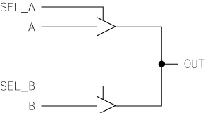
 Floating nodes are internal nodes of a circuit that are not driven to a logic 0 or logic 1. They should always be avoided. An example of a potential floating node is shown in Figure 5.17. If signals SEL_A and SEL_B are both not asserted, signal OUT will float to an unknown level. Downstream logic may interpret OUT as a logic 1 or a logic 0, or the floating signal may create a metastable state. In particular, any CMOS circuitry that uses signal OUT as an input will use up power because CMOS dissipates power when the input is in the threshold region. The signal OUT will typically float somewhere in the threshold region. Also, even if downstream logic is not using this signal, the signal can bounce up and down, causing noise in the system and inducing noise in surrounding signals.
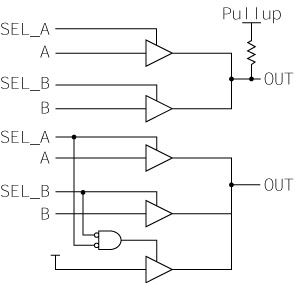
Two solutions to the floating node problem are shown in Figure 5.18. At the top, signal OUT is pulled up using an internal pull-up resistor. This simple fix ensures that when both select signals are not asserted, OUT will be pulled to a good logic level. Note that the pull up represented in the picture may be a passive resistor, or it may be an active pull up circuit that can be faster and more power conservative.