Designing with FPGAs and CPLDs
In this easy to follow guide, the author provides a look at the proprietary designs and methods of CPLDs and FPGAs available to managers, designers and engineers.
For a typical large-grained FPGA architecture, the normal method of designing state machines is not optimal. This is because the normal approach to FSMs tends to couple a few flip-flops that encode state to a large network of combinatorial logic that decodes the state. In an FPGA, though, large combinatorial networks must be built by aggregating several CLBs. Each single CLB may contain small lookup tables that can easily implement any eight or nine input combinatorial function. If you need a 10 input function, you need to spread the logic over two CLBs. Decoding the state representation used in classic FSM designs, can involve many CLBs. This means that routing becomes involved, significantly adding to the circuit delay, and slowing down the maximum clock speed for the design. An alternate design method, called one-hot state encoding, is better suited to FPGAs because it reduces the the number of inputs to the combinatorial network, thus reducing routing overhead and allowing better timing and thus faster clocks.
Figure 5.22 shows a small but typical state diagram for some simple state machine. Using the classic design methodology the four states would be represented as two state bits.
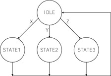
Figure 5.23 shows a typical design for this state machine, where the (S1, S0) states are defined as follows: IDLE (00), STATE1 (01), STATE2 (10), and STATE3 (11). Notice that although the number of flip-flops are minimized, the combinatorial logic is fairly large. As the...