Electronic Devices and Amplifier Circuits with MATLAB Computing, Second Edition
Emphasizing operational amplifiers and integrated devices used in digital circuits, this text presents a thorough discussion of state-of-the-art electronic devices.
This chapter begins with an introduction to operational amplifiers (op amps), characteristics, and applications. We will discuss the ideal op amp, analysis of circuits in the inverting and non-inverting configurations, and gain and bandwidth on circuit performance. We will also introduce some circuits consisting of op amps and non-linear devices, and analog computers.
The operational amplifier or simply op amp, is the most versatile electronic amplifier. It derives it name from the fact that it is capable of performing many mathematical operations such as addition, multiplication, differentiation, integration, and analog-to-digital conversion or vice versa. It can also be used as a comparator and electronic filter. It is also the basic block in analog computer design. Its symbol and pinouts are shown in Figure 5.1.
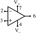
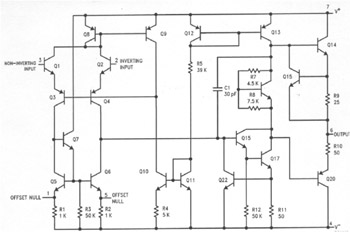
As shown above the op amp has two inputs but only one output For this reason it is referred to as differential input, single ended output amplifier. Figure 5.2 shows the internal construction of the popular 741 op amp. This figure also shows terminals V + and V ?. These are the voltage sources required to power up the op amp. Typically, V + is +15 volts and V ? is ?15 volts. These terminals are not shown in op amp circuits since they just provide power, and do not reveal any other useful information for the op amp s circuit analysis.