Electronic Devices and Amplifier Circuits with MATLAB Computing, Second Edition

Emphasizing operational amplifiers and integrated devices used in digital circuits, this text presents a thorough discussion of state-of-the-art electronic devices.
This appendix begins with a simple resistive attenuator which may be used to reduce the amplitude of a signal waveform. We will examine the conditions under which it is possible to ensure no distortion even if shunt capacitances are taken into consideration. Also, we will investigate the types of responses which are obtained with a step voltage input if the circuit is improperly adjusted.
Let us consider the simple resistor combination of Figure D.1(a).
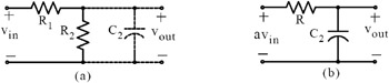
The presence of the stray capacitance C 2 in Figure D.1(a) represents an unavoidable condition since the output of the resistive attenuator in most cases is followed by the input capacitance of a stage of amplification. Using Thevenin s theorem, we can replace the circuit of (a) with that of (b) where R represents the parallel combination of R 1 and R 2 and a in av in is the attenuation factor. We could make both R 1 and R 2 very large so that the input impedance of the attenuator would be large enough to prevent loading down the input signal but his may produce a large rise time which would, in most cases, be unacceptable. This is explained below.
The rise time, denoted as t r, is defined as the time it takes the voltage to rise from 10% to 90% of its final value. It is an indication of how fast a circuit...