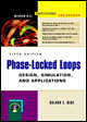
Phase-Locked Loops: Design, Simulation, and Applications, Fifth Edition
Chapter 1: Introduction to PLLs

1.1 Operating Principles of the PLL

The phase-locked loop (PLL) helps keep parts of our world orderly. If we turn on a television set, a PLL will keep heads at the top of the screen and feet at the bottom. In color television, another PLL makes sure that green remains green and red remains red (even if the politicians claim that the reverse is true).

A PLL is a circuit that causes a particular system to track with another one. More precisely, a PLL is a circuit synchronizing an output signal (generated by an oscillator) with a reference or input signal in frequency as well as in phase. In the synchronized-often called locked-state the phase error between the oscillator's output signal and the reference signal is zero, or remains constant.

If a phase error builds up, a control mechanism acts on the oscillator in such a way that the phase error is again reduced to a minimum. In such a control system the phase of the output signal is actually locked to the phase of the reference signal. This is why it is referred to as a phase-locked loop.

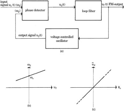
The operating principle of the PLL is explained by the example of the linear PLL (LPLL). As will be pointed out in Sec. 1.2, there exist other types of PLLs, e.g., digital PLLs (DPLLs), all-digital PLLs (ADPLLs), and software PLLs (SPLLs). Its block diagram is shown in Fig. 1.1a. The PLL consists of three basic functional blocks:


Figure 1.1:

UNLIMITED FREE
ACCESS
TO THE WORLD'S BEST IDEAS

SUBMIT
Already a GlobalSpec user? Log in.

This is embarrasing...

An error occurred while processing the form. Please try again in a few minutes.

Customize Your GlobalSpec Experience

Category: IC Phase-locked Loops (PLL)
Finish!
Privacy Policy

This is embarrasing...

An error occurred while processing the form. Please try again in a few minutes.