Practical Filters and Couplers: A Collection from Applied Microwave & Wireless
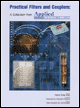
With contributions from more than 20 experts, these articles will show you how to use the latest design and testing techniques for filters, couplers and baluns.
 TABLE OF CONTENTS
 By Victor Koren
From APPLIED MICROWAVE & WIRELESS VOL.12, NO. 9, SEPTEMBER 2000
This article discusses the design of a variable frequency band-pass filter with constant characteristics across the frequency range.
A common way to design LC band-pass filters is to use parallel LC resonators with some coupling mechanism at the ends, to the source on one side, to the load on the other side and between the resonators.
The Q of the resonators control the characteristics of the band-pass filter (BPF). The Q loaded/ Q unloaded ratio controls the insertion loss of the BP; the Q loaded controls the fractional bandwidth. ( Q unloaded: the parallel loss resistance of the resonator divided by the reactance of one of the elements of the resonator, at resonant frequency; Q loaded: the parallel connection of the parallel loss resistance of the resonator with the parallel value of the load across the resonator divided by the reactance of one of the elements of the resonator).
Frequently, used BPF use capacitors or inductors as top coupling elements between the resonators and terminations. Varying the center frequency of the BPF by changing the value of the resonators capacitor will affect the coupling between the BPF resonators and terminations, changing its characteristics.
Figure 1, for example, shows a capacitor coupled 30 MHz BPF, with 5 percent ?3 dB points bandwidth, 5 dB insertion loss and flat band-pass response. Each inductor is modeled with...