Practical Filters and Couplers: A Collection from Applied Microwave & Wireless
With contributions from more than 20 experts, these articles will show you how to use the latest design and testing techniques for filters, couplers and baluns.
 TABLE OF CONTENTS
 The author offers three simple techniques for the design of higher impedance filters
By Gary A.Breed
From APPLIED MICROWAVE & WIRELESS, VOL. 9, NO. 3, MAY/JUNE 1997
Many modern systems operate at a standard impedance of 50 ohms, but a band-pass filter designed for that impedance may require impractical inductance values of inductor Qs. The solution is a filter designed for a higher impedance, with some type of impedance matching network. Here are three simple matching methods.
Figure 1 shows a double-tuned bandpass filter structure. Without elaborating on its design, assume that we have selected design parameters and components that result in R L=2000 ohms.

No additional components are needed to use a tapped inductor (Figure 2(a)) as the matching method, although an additional connection must be made. Theoretically, the tapped inductor is identical to the inductive link (Figure 2(b)) in the way an autotransformer is related to a conventional transformer. The link method requires winding the turns of the link and provides DC isolation.
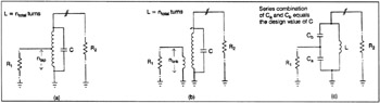
The configuration of the tapped inductor or link is calculated by the following turns ratio formula:
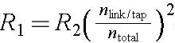
Therefore,
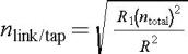
In the example circuit, if the inductor was implemented with a 24-turn winding on an iron powder toroid core, the tap of link would be 3.795 turns, which...