Practical Filters and Couplers: A Collection from Applied Microwave & Wireless
With contributions from more than 20 experts, these articles will show you how to use the latest design and testing techniques for filters, couplers and baluns.
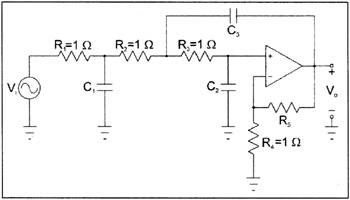
Figure 3 shows a low-pass filter with selectable gain. The transfer function for this filter is given in Equation (1) where
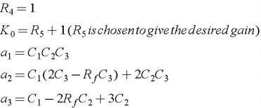
Backward-solving and substitution of these equations does not result in a simple cubic.
Let M= ? 2+ ? 2
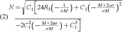
This expression must be solved numerically for C 1 :
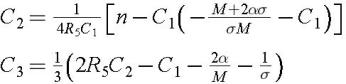
Once C 1 is found, the other capacitors are
A list of capacitor values for various gain and filter characteristics is given in Tables 1 4 in the appendix.
| Linear Gain K 0 | C1 | C2 | C3 | R5 (R4=1 ?) |
|---|---|---|---|---|
| 1.5 | 1.59448 | 0.529798 | 1.18383 | 0.5 |
| 2 | 1.70585 | 0.676115 | 0.867076 | 1 |
| 4 | 2.00002 | 1.00002 | 0.500006 | 3 |
| 6 | 2.20464 | 1.19602 | 0.379266 | 5 |
| 8 | 2.36801 | 1.34386 | 0.314254 | 7 |
| 10 | 2.50608 | 1.46530 | 0.272330 | 9 |
| 12 | 2.62667 | 1.56975 | 0.242540 | 11 |
| 14 | 2.73432 | 1.66219 | 0.220033 | 13 |
| 16 | 2.83194 | 1.74564 | 0.202293 | 15 |
| 18 | 2.92152 | 1.82202 | 0.187869 | 17 |
| 20 | 3.00450 | 1.89272 | 0.175858 | 19 |
| Linear Gain K 0 | C1 | C2 | C3 | R5 (R4=1 ?) |
|---|---|---|---|---|
| 1.5 | 1.80347 | 0.534989 | 1.31672 | 0.5 |
| 2 | 1.92172 | 0.692807 | 0.954213 | 1 |
| 4 | 2.22923 | 1.04493 | 0.545386 | 3 |
| 6 | 2.44186 | 1.25983 | 0.412965 | 5 |
| 8 | 2.61181 | 1.42244 | 0.341958 | 7 |
| 10 | 2.75576 | 1.55614 | 0.296248 | 9 |
| 12 | 2.88180 | 1.67115 | 0.263796 | 11 |
| 14 | 2.99457 | 1.77291 | 0.239291 | 13 |
| 16 | 3.09703 | 1.86472 | 0.219982 | 15 |
| 18 | 3.19123 | 1.94873 | 0.204285 | 17 |
| 20 | 3.27863 | 2.02643 | 0.191216 | 19 |