Practical Filters and Couplers: A Collection from Applied Microwave & Wireless
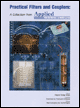
With contributions from more than 20 experts, these articles will show you how to use the latest design and testing techniques for filters, couplers and baluns.
Adding one component provides some restoration of symmetry
By Richard M.Kurzrok, PE
From APPLIED MICROWAVE & WIRELESS, VOL.11, NO. 10, OCTOBER 1999
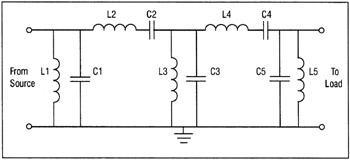
Band-pass filter transmission specifications usually require amplitude responses with arithmetic symmetry. The conventional band-pass filter, with a schematic as shown in Figure 1, employs a ladder network of alternate grounded shunt resonators and floating series resonators. This filter has inherent geometric amplitude symmetry and is customarily designed for bandwidths in excess of 30 percent. Most commonly used band-pass filters for small and moderate bandwidths have amplitude responses that are not symmetrical. Special designs or various corrective measures are used to alleviate this situation. This article discusses how to correct the amplitude symmetry of the popular top coupled band-pass filter by adding an inductive bridging coupling.
Alternate band-pass filter circuits can be designed for amplitude symmetry. Rhea [1] has used the arithmetic transform method to transform the odd number shunt resonators of a conventional band-pass filter into series resonators while using shunt coupling capacitors, often referred to as bottom-C coupling. Cuthbert [2] has judiciously used various network transformations to improve filter response shape symmetry. However, the use of network transformations is not the focus of this article. For further information, consult the references.
Partial amplitude correction can be obtained by modifications to well-known band-pass filter circuits. The popular top-C coupled band-pass filter uses series capacitors between shunt resonators for all filter couplings. The top-L coupled band-pass filter...