Practical Filters and Couplers: A Collection from Applied Microwave & Wireless
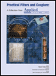
With contributions from more than 20 experts, these articles will show you how to use the latest design and testing techniques for filters, couplers and baluns.
The transformers and stepped-gain attenuator required for a classical directional coupler have been successfully integrated onto a single S-Band MMIC that features adjustable coupling over a 30 dB range
By Mitchell Shifrin, Christopher Lyons, Wes Grammer and Peter Katzin
From APPLIED MICROWAVE & WIRELESS, VOL. 8, NO. 4, NOVEMBER/DECEMBER 1996
Directional couplers are the principal elements in beam-forming networks for phased-array antennas in applications such as monopulse radar. In systems that use an array of monolithic transmit and receive (T/R) modules, a coupler in MMIC form could be integrated in the module, saving space and lowering overall cost. This paper describes such a monolithic directional coupler.
Figure 1 illustrates the functions of the coupler in a monopulse system. In transmit mode, the coupler must pass the exciter signal with minimum loss and phase distortion. In receive mode, the coupled port amplitude must be controllable over a broad range without affecting other coupler parameters such as directivity and isolation. The variable attenuator shown in the sum channel is another element in the beam forming network. It must have minimum phase change with attenuation and good linearity. This article presents the design and measured data for both components.
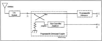
The programmable directional coupler MMIC consists of two elements: a lumped-element, broadband coupler with a novel planar transformer layout and a variable-gain amplifler, adjustable over a ?15 dB range in 30 linear steps. The variable attenuator MMIC is digitally programmable in...